Chevrolet Cruze Repair Manual: Air Conditioning Compressor and Condenser Hose Replacement (1.6L LDE, LXV, and 1.8L 2H0)
Removal Procedure
- Recover the refrigerant. Refer to Refrigerant Recovery and Recharging
- Remove front bumper fascia. Refer to Front Bumper Fascia Replacement
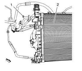
- Remove A/C compressor and condenser hose nut (1) from A/C condenser (2).
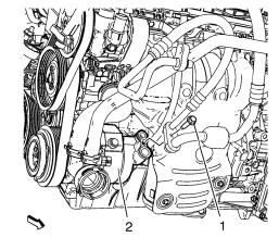
- Remove A/C compressor and condenser hose bolt (1) from A/C compressor (2).
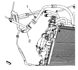
- Remove A/C compressor and condenser hose nut (1) from refrigerant hose (2).
- Remove A/C compressor and condenser hose.
Installation Procedure
Note: Use NEW O-ring seals. Refer to Air Conditioning O-Ring Seal Replacement
- Install A/C compressor and condenser hose.
Caution: Refer to Fastener Caution in the Preface section.
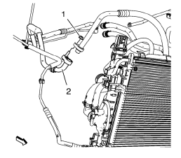
- Install A/C compressor and condenser hose nut (1) to refrigerant hose (2). Tighten nut to 19 N·m (14 lb ft).
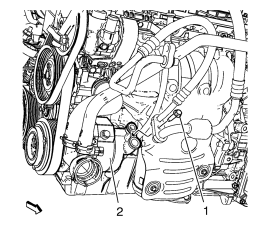
- Install A/C compressor and condenser hose bolt (1) to A/C compressor (2). Tighten bolt to 19 N·m (14 lb ft).
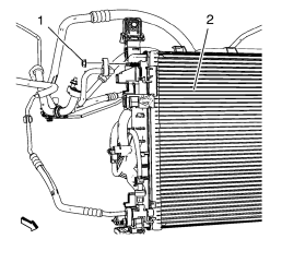
- Install A/C compressor and condenser hose nut (1) to A/C condenser (2). Tighten nut to 19 N·m (14 lb ft).
- Install front bumper fascia. Refer to Front Bumper Fascia Replacement
- Evacuate and charge the refrigerant system. Refer to Refrigerant Recovery and Recharging
 Air Conditioning Compressor and Condenser Hose Replacement (1.6L LXT)
Removal Procedure
Recover the refrigerant. Refer to Refrigerant Rec overy and
Recharging.
Remove front bumper fascia. Refer to Front Bumper Fascia Replacement.
Remove A/ ...
 Air Conditioning Evaporator Hose Assembly Replacement
Preliminary Procedures
Recover the refrigerant. Refer to Refrigerant Recovery and Recharging.
Remove the headlamp - right side. Refer to Headlamp Replacement.
Loosen power steering fluid r ...
Other materials:
Frontal SIR System Description
The frontal supplemental inflatable restraint (SIR) system consists of the
following components:
AIR BAG indicator located in the instrument cluster
Inflatable restraint sensing and diagnostic module (SDM)
Inflatable restraint passenger presence detection system
Inflatable restraint Pass ...
Installation Procedure
Note: If the location of the original plug weld holes can not be
determined, space the plug weld holes every 40 mm (1½ in).
Drill 8 mm (5/16 in) for plug welding along the edges of the rear floor
panel filler as noted from the original
panel.
Clean and prepare the atta ...
Removal Procedure
Warning: Refer to Approved Equipment for Collision Repair Warning in the
Preface section.
Warning: Refer to Collision Sectioning Warning in the Preface section.
Warning: Refer to Glass and Sheet Metal Handling Warning in the Preface section.
Disable the SIR System. Refer to SIR Disabling ...
