Chevrolet Cruze Repair Manual: Front Wheel Drive Shaft Replacement - Right Side
Special Tools
- CH-313 Slide Hammer
- CH-6003 Axle Shaft Remover
- CH-49376 Holding Wrench
- CH-49400 Hub Spindle Remover
- DT-6332 Seal Protector
- EN-956-1 Extension
For equivalent regional tools, refer to Special Tools.
Removal Procedure
Warning: To prevent personal injury and/or component damage, do not allow the weight of the vehicle to load the front wheels, or attempt to operate the vehicle, when the wheel drive shaft(s) or wheel drive shaft nut(s) are removed. To do so may cause the inner bearing race to separate, resulting in damage to brake and suspension components and loss of vehicle control.
Caution: Wheel drive shaft boots, seals and clamps should be protected from sharp objects any time service is performed on or near the wheel drive shaft(s). Damage to the boot(s), the seal(s) or the clamp(s) may cause lubricant to leak from the joint and lead to increased noise and possible failure of the wheel drive shaft.
- Raise and suitably support the vehicle. Refer to Lifting and Jacking the Vehicle.
- Remove the tire and wheel assembly. Refer to Tire and Wheel Removal and Installation.
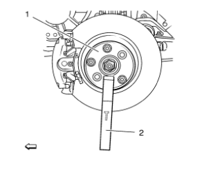
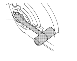
- Using the CH-49376 holding wrench (1) with EN-956-1 extension (2).
Note: DO NOT re-use the wheel drive shaft nut. Discard the nut and replace with NEW.
- Remove the wheel drive shaft nut (2) from the wheel drive shaft (1).
Caution: Support the brake caliper with heavy mechanic wire, or equivalent, whenever it is separated from its mount and the hydraulic flexible brake hose is still connected. Failure to support the caliper in this manner will cause the flexible brake hose to bear the weight of the caliper, which may cause damage to the brake hose and in turn may cause a brake fluid leak.
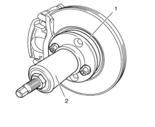
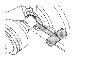
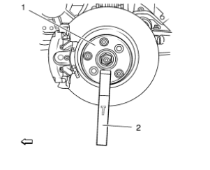
- Using the CH-49400 remover (2), separate the brake rotor and wheel bearing/hub assembly (1).
- Remove the outer tie rod assembly from the steering knuckle. Refer to Steering Linkage Outer Tie Rod Replacement.
- Remove the ball joint from the steering knuckle. Refer to Lower Control Arm Replacement.
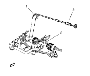
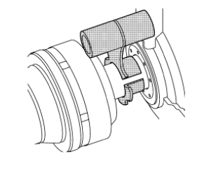
- Using the CH-313 slide hammer (2) with CH-6003 remover (1) remove the wheel drive shaft (3) from the vehicle.
Installation Procedure
- Install the DT-6332 protector into the differential output shaft seal.
Note: In order to prevent lubricant leaks, use care when installing the wheel drive shaft to the differential. Do not damage the oil seal. Replace the oil seal if it becomes nicked, distorted, or otherwise damaged.
- Carefully install the wheel drive shaft into the differential until the splines are past the DT-6332 protector .
- Remove the DT-6332 protector from the differential output shaft seal.
- Install the wheel drive shaft into the differential until the retaining ring is fully seated.
- Confirm that the front wheel drive shaft retaining ring is properly seated by holding the inner housing and pull the inner housing outward.
- Install the front wheel drive shaft into the front wheel bearing/hub.
- Install the ball joint to the steering knuckle. Refer to Lower Control Arm Replacement.
- Install the outer tie rod assembly at the steering knuckle. Refer to Steering Linkage Outer Tie Rod Replacement.
Caution: Refer to Fastener Caution in the Preface section
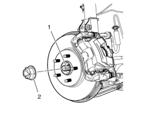
- Install the NEW wheel drive shaft nut (2) to the wheel drive shaft (1) tighten in 3 passes.
- Using the CH-49376 holding wrench (1) with EN-956-1 extension (2).
- Using a torque wrench and the appropriate size socket, tighten the wheel drive shaft nut to 150 N·m 111 (lb ft).
- Release the wheel drive shaft nut (2) trough 45°.
- Retighten the wheel drive shaft nut (2) to 250 N·m (185 lb ft).
- Install the tire and wheel assembly. Refer to Tire and Wheel Removal and Installation.
- Lower the vehicle.
- Inspect the transaxle fluid level. Refer to Transmission Fluid Check.
 Front Wheel Drive Shaft Replacement - Left Side
Special Tools
CH-313 Slide Hammer
CH-6003 Axle Shaft Remover
CH-46376 Holding Wrench
CH-49400 Hub Spindle Remover
DT-6332 Seal Protector
EN-956-1 Extension
For equivalent regional too ...
 Rear Brake Rotor Replacement
Special Tools
CH 41013 Rotor Resurfacing Kit
CH 42450-A Wheel Hub Resurfacing Kit
For equivalent regional tools, refer to Special Tools.
Removal Procedure
Warning: Refer to Brake Dust Warni ...
Other materials:
Driver or Passenger Seat Replacement
Removal Procedure
Warning: Refer to SIR Warning in the Preface section.
Warning: When carrying a live inflator module, make sure the bag
opening is pointed away from you. This minimizes the chance of
injury in the case of an accidental deployment. Never carry the inflator module
by the wi ...
SIR Service Precautions
SIR Service Precautions
Warning: When performing service on or near the SIR components or
the SIR wiring, the SIR system must be disabled. Failure to observe
the correct procedure could cause deployment of the SIR components. Serious
injury can occur. Failure to observe the correct procedure
...
Rear Side Door Window Replacement
Preliminary Procedures
Position the window approximately half way down in the door.
Remove the water deflector. Refer to Rear Side Door Water Deflector
Replacement.
Remove the outer sealing strip. Refer to Rear Side Door Window Outer
Sealing Strip Replacement.
Rear Side ...
