Chevrolet Cruze Repair Manual: Horns
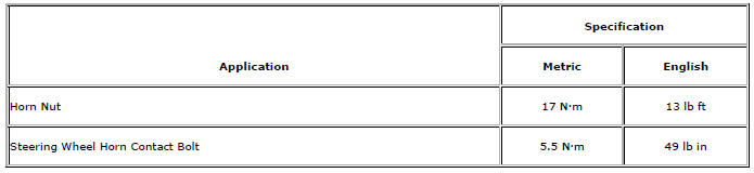
Specifications
Horn Replacement
Preliminary Procedure
Remove the front bumper fascia. Refer to Front Bumper Fascia Replacement.
- Horn Nut
Caution: Refer to Fastener Caution in the Preface section.
Tighten 17 N·m (13 lb ft)
- Horn
Tip Disconnect electrical connectors.
Steering Wheel Horn Contact Replacement
Preliminary Procedure
Remove inflatable restraint steering wheel module. Refer to Steering Wheel Inflatable Restraint Module Replacement.
- Steering Wheel Horn Contact Bolt (Qty: 3)
Caution: Refer to Fastener Caution in the Preface section.
Tighten 5.5 N·m (49 lb in)
- Steering Wheel Horn Contact
Tip
Disconnect the electrical connector.
Horn System Description and Operation
System Description
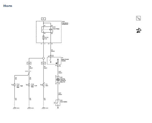
The horn system consists of the following components:
- F51UA 15A fuse
- Underhood fuse block (contains a non-serviceable PCB Horn relay)
- Horn switch
- Horn
- Body control module (BCM)
System Operation
The vehicle horn is activated whenever the horn switch is depressed.
The BCM commands the horns ON under any of the following conditions:
- When the content theft deterrent system detects a vehicle intrusion--For further information refer to Content Theft Deterrent (CTD) Description and Operation.
- When the keyless entry system is used to lock the vehicle, a horn chirp may sound to notify the driver that the vehicle has been locked. The notification feature may be enabled or disabled through personalization. For further information refer to Keyless Entry System Description and Operation.
Circuit Operation
The BCM controls the horn operation, when the horn switch is pressed, it closes a switch pulling the horn signal circuit low. When the BCM detects the drop in voltage in the horn switch signal circuit, it energizes the PCB Horn relay which provides B+ voltage to the horn control circuit, sounding the horn.
When the vehicle is in the Off Power Mode the BCM will attempt to detect a stuck or continuously activated horn switch. When enabled, activation of the horn will be limited to 10 seconds to protect the horn from excessive use.
 Rear Window Defogger Description and Operation
Rear Window Defogger System Components
The rear window defogger system consists of the following components:
HVAC Control Module
HVAC Control Head
Rear Window Defogger Relay
Rear Defogger G ...
 Lighting
Specifications
Headlights/Daytime Running Lights (DRL) Schematics
Interior Lights Schematics
...
Other materials:
Generator Air Conditioning Compressor,Power Steering Pump Belt Replacement
Removal Procedure
Raise the vehicle full height. Refer to Lifting and Jacking the Vehicle.
Remove the front compartment splash shield. Refer to Front Compartment
Splash Shield Replacement.
Rotate the drive belt tensioner bolt (2) clockwise.
Remove the drive belt (1) while pullin ...
US English/Metric Conversion
Decimal and Metric Equivalents
Arrows and Symbols
This service manual uses various symbols in order to describe different
service operations.
Front of Vehicle
View Detail
View Detail
Ambient Air Mixed with Another Gas or Indicate Temperature Chan ...
Installation Procedure
Install NEW stabilizer shaft insulators (1) to stabilizer shaft (2) so
that the slit in the insulator is facing the rear of the vehicle.
Install the insulator c 2. lamp to the insulator:
2.1. Position the clamp (2) over on the insulator.
2.2. Use two M8 bolts (1, 3) with 40 ...
