Chevrolet Cruze Repair Manual: Installation Procedure
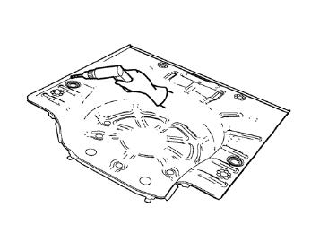
- Align the rear compartment floor panel.

Drill 8 mm (5/16 in) for plug welding along the edges of the rear compartment floor panel as noted from the original panel.
- Clean and prepare the attaching surfaces for welding.
- Position the rear compartment floor panel on the vehicle.
- Verify the fit of the rear compartment floor panel.
- Clamp the rear compartment floor panel into position.

- Plug weld accordingly.

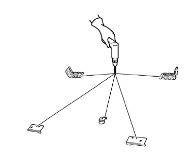
- Drill 8 mm (5/16 in) for plug welding along the edges of the floor panel rear reinforcement, the spare wheel carrier bracket and the rear wheelhouse panel rear brace as noted from the original panel.
- Clean and prepare the attaching surfaces for welding.
- Position the floor panel rear reinforcement, the spare wheel carrier bracket and the rear wheelhouse panel rear brace on the vehicle.
- Verify the fit of the floor panel rear reinforcement, the spare wheel carrier bracket and the rear wheelhouse panel rear brace.

- Plug weld accordingly.
- Weld accordingly the weld studs as noted.
- Apply the sealers and anti-corrosion materials to the repair area, as necessary. Refer to Anti-Corrosion Treatment and Repair.
- Paint the repaired area. Refer to Basecoat/Clearcoat Paint Systems.
- Install all related panels and components
- Connect the negative battery cable. Refer to Battery Negative Cable Disconnection and Connection.
- Enable the SIR system. Refer to SIR Disabling and Enabling.
 Removal Procedure
Warning: Refer to Approved Equipment for Collision Repair Warning in the
Preface section.
Warning: Refer to Glass and Sheet Metal Handling Warning in the Preface section.
Disable the SIR Syst ...
 Rear Compartment Floor Panel Sectioning (MIG-Brazing)
Note: According to different corrosion warranties, only the
regional mandatory joining methods are allowed. ...
Other materials:
Engine Exhaust
WARNING
Engine exhaust contains carbon monoxide (CO) which cannot be seen or smelled.
Exposure to CO can cause unconsciousness and even death.
Exhaust may enter the vehicle if:
Х The vehicle idles in areas with poor ventilation (parking garages, tunnels, deep
snow that may block underbody air ...
Installation Procedure
Remove the front wheelhouse rear panel brace (1) from service panel.
Create 6 x 20 mm (4/16 x 12/16 in) slots for MIG-brazing along the edges
of the front wheelhouse (1).
Clean and prepare the attaching surfaces for brazing.
Note: In MIG-brazing areas 50 mm (2 in) must b ...
Front Side Door Wiring Harness Replacement
Preliminary Procedure
Remove the front side door inner panel trim. Refer to Front Side Door Trim
Replacement.
Front Side Door Wiring Harness
Warning: Unless directed otherwise, the ignition and start switch must be
in the OFF or LOCK position, and all electrical
loads must be OFF before ...
