Chevrolet Cruze Repair Manual: Windshield Wiper Arm Replacement
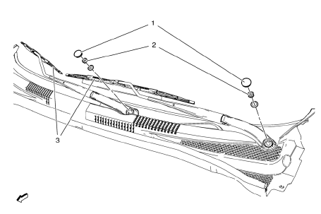
- Windshield Washer Arm Finish Cap
Tip
Use a small flat-bladed tool to remove finish cap.
Special Tools
BO-6626 Wiper Arm Puller
For equivalent regional tools, refer to Special Tools.
- Windshield Washer Arm Nut
Caution: Refer to Fastener Caution in the Preface section.
Procedure
- Locate the transparent circle with a black dot in the center at the lower windshield blackout area.
- Position the wiper arm to the pivot shaft so that the wiper blade is centered across the transparent circle.
- Lift the arm blade portion while pushing down the arm onto the pivot shaft.
- Install the wiper arm nut.
- Hold the wiper arm stationary in position as previously stated.
- Torque the wiper arm nut.
- Release the wiper arm assembly.
- Repeat the same procedure for the other wiper arm.
Tighten
24.5 N·m (18 lb ft)
- Windshield Washer Arm Assembly
Tip
Use the wiper arm puller if the arm fails to release from the wiper motor pivot shaft.
Windshield Wiper Blade Replacement
Preliminary Procedure
Raise the wiper arm up off the windshield.
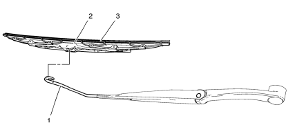
- Windshield Washer Arm Assembly
- Windshield Wiper Arm Blade Removal Tab
Procedure
- Push inward the square tab at the center top side of the wiper blade.
- Rotate the wiper blade downward slightly.
- Slide the wiper blade from the wiper arm.
- Carefully release the wiper arm back to the windshield.
- Windshield Washer Blade Assembly
Tip
Discard if rubber appears worn or does not wipe the windshield clean.
Windshield Wiper Motor Replacement
Preliminary Procedures
- Remove the windshield wiper arms. Refer to Windshield Wiper Arm Replacement
- Remove the air inlet grille panel. Refer to Air Inlet Grille Panel Replacement.
- Remove the wiper drive system module.
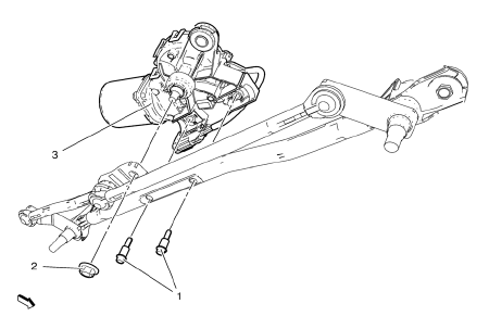
- Windshield Wiper Motor Bolts (Qty: 2)
Caution: Refer to Fastener Caution in the Preface section.
Tighten 10 N·m (89 lb in)
- Windshield Wiper Motor Nut
Tighten 10 N·m (89 lb in)
- Windshield Wiper Motor Assembly
Windshield Wiper Transmission Replacement (Right Hand Drive)
Preliminary Procedures
- Remove the wiper arms. Refer to Windshield Wiper Arm Replacement.
- Remove the air inlet grille panel. Refer to Air Inlet Grille Panel Replacement.
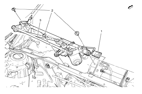
- Electrical Connector
- Windshield Wiper Transmission Bolt (Qty: 3)
Caution: Refer to Fastener Caution in the Preface section.
Tighten 10 N·m(89 lb in)
- Windshield Wiper Transmission
Windshield Outside Moisture Sensor Cover Replacement
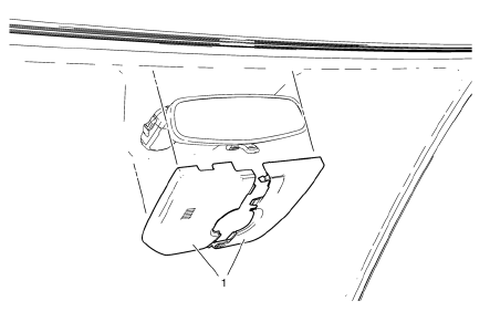
- Windshield Outside Moisture Sensor Cover Assembly
Windshield Outside Moisture Sensor Replacement
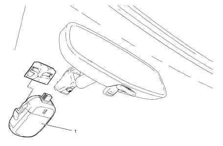
Preliminary Procedure
Remove the windshield outside moisture sensor cover. Refer to Windshield Outside Moisture Sensor Cover Replacement.
- Windshield Outside Moisture Sensor
Tip
Pull the windshield outside moisture sensor down to remove from bracket.
Wiper Blade Element Cleaning
Lift each blade assembly off of the windshield and clean the element with a cloth saturated with full strength washer solvent. Then rinse the blade assemblies with clear water.
Windshield Wiper Arm Adjustment
Measuring point for windscreen wiper arms: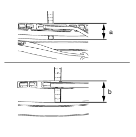
Upper edge of water deflector (rubber lip) to wiper arm attachment point.
Note: Position the wiper arm to the basic setting.
- Driver side (a) approximately 6.5 cm (2.6 in)
- Passenger side (b) approximately 8.5 cm (3.3 in).
 Windshield Washer Pump Seal Replacement
Removal Procedure
Open the hood.
Remove the windshield washer pump. Refer to Windshield Washer Pump
Replacement
Using a small flat-bladed tool, remove the washer pump terminal seal (1) ...
 Wiper/Washer System Description and Operation
Wiper/Washer System Components
The wiper/washer system consists of the following electrical components:
Windshield Wiper Relay
Windshield Wiper Speed Control Relay
Windshield Washer Pump Rela ...
Other materials:
Steering Column in Lock Position Caution
Caution: With wheels of the vehicle facing straight ahead, secure
the steering wheel utilizing steering column anti-rotation pin, steering
column lock, or a strap to prevent rotation. Locking of the steering column will
prevent damage and a possible malfunction of the SIR
system. The steering ...
Removal Procedure
Warning: Refer to Approved Equipment for Collision Repair Warning in the
Preface section.
Warning: Refer to Glass and Sheet Metal Handling Warning in the Preface section.
Disable the SIR System. Refer to SIR Disabling
and Enabling.
Disconnect the negative battery cable. Refer to ...
Climate Controls
The heating, cooling, defrosting, and ventilation for the vehicle can be controlled
with these systems.
Vehicles without Air Conditioning
1. Temperature Control
2. Bi-level Air Mode
3. Floor Air Mode
4. Vent Air Mode
5. Fan Control
6. Driver and Passenger Heated Seats (If Equipped)
7. Re ...
