Chevrolet Cruze Repair Manual: Wiper/Washer System Description and Operation
Wiper/Washer System Components
The wiper/washer system consists of the following electrical components:
- Windshield Wiper Relay
- Windshield Wiper Speed Control Relay
- Windshield Washer Pump Relay
- Rain Sensor (optional)
- Windshield Washer Fluid Pump
- Windshield Wiper Motor
- Window Wiper/Washer Switch
- Body Control Module (BCM)
Windshield Wiper System
The BCM determines the front wipe/wash system mode of operation by monitoring several signals from the front wipe/wash switch as indicated in the wiper switch.
The front wipe/wash switch receives a reference ground signal from the BCM. Each input of the BCM provides a switched battery pull-up for each front wiper/washer switch output signal it receives. All the BCM inputs are recognized as active when the wiper switch provides a path to the referenced ground signal. The first signal received by the BCM is the result of 6 resistors in the front wiper switch configured as a resistor ladder network. This signal is connected to a BCM analog to digital input. Depending on the function selected (High, Low, Intermittent 1 to 5, Mist, Off), the front wiper control switch connects a different set of resistors into the circuit resulting in different voltages appearing on the BCM A/D input. By monitoring this voltage, the BCM determines how to control the wiper motor On/Off Relay. It should be noted that High, Low, and Mist all have the same value on this signal circuit. The second signal received from the front wiper switch is active only when the front wiper switch is in the high speed wiper position. When the wiper switch is not in the high speed position, the switch is open and the signal circuit is pulled to battery by the BCM. When the wiper switch is in the high speed position, the switch pulls the circuit low. The BCM determines how to control the Wiper high/low speed relay from this input. The third signal received from the front wiper switch is from the momentary windshield wash control switch. When the washer switch is not active the switch is open and the signal circuit is pulled to battery by the BCM. When the washer switch is active, the switch pulls the circuit low. The BCM controls the windshield wash and windshield wash activated wiper operation based on this input.
The BCM controls front wiper motor operation through two output signals and the monitoring of one input signal. The two outputs (one high side drive, one low side drive) are used to control two external wiper motor relays: front wiper motor on/off relay: which provides the wiper motor with battery power when it is activated by the high side drive signal (switched battery) from the BCM. When left deactivated, the normally closed contacts provide a ground to the wiper motor. Wiper high/low speed relay: when activated by a low side drive signal (ground) from the BCM, it switches the power supplied by the wiper motor's on/off relay to the motors high speed input. When left deactivated, the normally closed contacts connect the power supplied by the wiper motor's on/off relay to the motor's low speed input. The input used by the BCM is from the park switch located in the wiper motor assembly. When the wiper blades are not in the park position, the wiper park switch is open and the circuit is pulled up to battery by the BCM. When the wiper blades are in the park position at the bottom of the glass, the wiper park switch closes to ground pulling the park signal circuit low.
To initiate low speed operation, the BCM only energizes the front wiper motor on/off relay. This allows battery voltage from the wiper fuse to be applied through the switched contacts of the wiper motor on/off relay, through the normally closed contacts of the wiper high/low speed relay, to the low speed control circuit of the windshield wiper motor.
The BCM provides redundant circuitry which places battery power on its wiper motor on/off relay output with activation of its low assertion high speed wiper switch input. The BCM shall be capable of doing this, even if the module has lost all microprocessor control. This redundant circuit shall supply power while in the RUN and CRANK power modes. however; while in the CRANK power mode, the pass through shall only be active if the BCM is NOT in a computer operating properly state.
To initiate high speed operation, the BCM energizes both the front wiper motor on/off relay and the wiper high/low speed relay. This allows battery voltage from the wiper fuse to be applied through the switched contacts of the wiper motor on/off relay, through the switched contacts of the wiper high/low speed relay, to the high speed control circuit of the windshield wiper motor.
In order to perform an accurate read of the park switch and to ensure the wipers will come to rest while still in the park position, parking of the wipers only occurs while in a low speed wiper mode. This requires that if the wipers are performing a high speed wiper operation at the time they are required to park, the BCM shall transition the Wipers to low speed by deactivating the wiper high/low relay before attempting to park. In order to park the wipers, the BCM monitors the park circuit until the park switch pulls the park circuit to ground. At this time, the BCM will immediately deactivate the wiper motor on/off relay. The relay contacts will switch back to their normally closed position and will apply ground to the wiper motor power inputs through the normally closed contacts of the wiper high/low relay. This deactivates and dynamically brakes the wiper motor in the park position. When the wiper switch is turned to the OFF position while the wiper motor is somewhere in mid-cycle, the BCM will continue to operate the motor until the wipers reach the park position. If the BCM is running the wiper motor and does not see a state transition of the park switch after 8 s, the wipers will stop immediately when the wiper switch is turned to OFF. If the ignition is turned OFF while the wipers are in mid-cycle, the wipers will stop immediately, regardless of position. The BCM will park the wipers next time the ignition is turned ON.
The windshield wiper system MIST operation is identical to LOW speed operation, except that the MIST switch is a press and release type switch. When the wiper switch is moved to the MIST position and released, low speed wiper motor operation is started and will continue until 1 cycle is complete. If the wiper switch is moved to the MIST position and held, the wiper motor will operate in the LOW speed mode until the switch is released.
Windshield wiper intermittent operation is a low speed wiper motor function with a variable delay interval between the wiper motor cycles.
The duration of the delay is controlled by the front wiper control switch's intermittent 1 to intermittent 5 settings. The wiper operation is as follows:
- The BCM will initiate a single wipe by activating its front wiper ON/OFF relay output.
- At the completion of a single wipe, the BCM will park the wipers as described above.
- The BCM will then pause the wipers in their park position for the time duration associated with intermittent delay switch setting.
- When the delay time expires repeat Steps 1 and 3 until the system is turned off or taken out of intermittent mode. If the wiper switch is moved from a longer delay interval to a shorter delay interval, the BCM will command an immediate wipe cycle and reset the delay timer to the shorter delay interval.
Intermittent wiper operation may be vehicle speed sensitive. When enabled, the speed compensated intermittent feature causes the intermittent wiper delay intervals to become shorter as a function of increased speed. As vehicle speed is reduced the intervals will become closer to the predetermined.
Intermittent wiper operation may be vehicle speed sensitive. When enabled, the speed compensated intermittent feature causes the intermittent wiper delay intervals to become shorter as a function of increased speed. As vehicle speed is reduced the intervals will become closer to the predetermined.
Windshield Washer System
The BCM controls the windshield wash operation and windshield wash activated wiper operation. When the BCM detects the activation of the momentary windshield wash control switch, it activates its washer pump relay drive output which supplies battery power to the coil of the washer pump relay. This energizes the relay, which switches battery power to the pump motor. The BCM will also activate continuous low speed windshield wipes as described above. Upon deactivation of the windshield wash control switch, the wiper control module (BCM) shall deactivate the wash motor and will also park the wiper motor as described above unless the drip wipe feature is enabled. On some vehicles the drip wipe feature will be enabled and cause the system to provide additional wiping of the windshield after the switch has been released and fluid is no longer being applied. The front wash feature may attempt to detect a stuck switch. When enabled, activation of the wash feature shall be limited to 10 s.
Rain Sense Mode and Rain Sense Indicator
When this feature is activated on rain sense equipped vehicles, the wiper subsystem performs front windshield wipes according to the amount of moisture detected on the windshield. The BCM will control the wiper motor speed, as indicated above, based on wipe requests that it receives from a moisture sensor (rain sense module) which is mechanically attached to the windshield through a windshield mounted optic coupler. The system uses a master/slave configuration utilizing a Local Interconnect Network (LIN) based serial data communication system. The BCM is designated as the master, while the rain sense module is designated the slave. As the system master, the BCM uses the LIN serial communication bus to enable or disable rain sense module operation, communicate wiper control switch settings, and wiper motor position information to the rain sense module. The rain sense module requests wiper motor function, and provides the BCM with system status and diagnostic information for diagnostic reporting. When this feature is present, the BCM uses the front wiper control switch's intermittent 1 thru intermittent 5 settings to activate the system and to act as the automatic wiper sensitivity control. This allows the driver to adjust the moisture level at which the rain Sensor requests the BCM to automatically wipe the windshield.
The intermittent 1 setting corresponds to the lowest sensitivity and intermittent 5 the highest sensitivity.
Some vehicles (calibratable) shall display an AUTO front wiper indicator when the feature is active. This indicator shall notify the driver of the vehicle that the rain sensor is ready to perform automatic wiping of the windshield upon detection of moisture.
This indicator shall be requested when all of the following are true:
- Power mode is RUN
- If single steering column switch equipped: The front wiper switch is SENSITIVITY 1 through SENSITIVITY 5.
- If dual steering column stalk equipped: The front wiper switch stalk angle is SENSITIVITY.
The above indicator shall be turned OFF when any of the following become true:
- Power mode becomes OFF, CRANK or ACCESSORY.
- Front wiper switch is changed to OFF, MIST, LOW or HIGH.
Special Tools and Equipment
 Windshield Wiper Arm Replacement
Windshield Washer Arm Finish Cap
Tip
Use a small flat-bladed tool to remove finish cap.
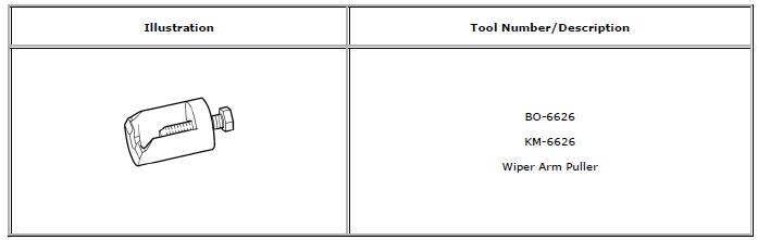
Special Tools
BO-6626 Wiper Arm Puller
For equivalent regional tools, refer to Special Tools.
...
 Roof
Roof
Specifications
Sunroof Schematics
Sunroof Component Views
Sunroof Frame
Sunroof Sunshade
Sunroof Window
Sunroof Window Seal
Sunroof Housing Rear Drain Hose
Sunroof ...
Other materials:
Air Conditioning Compressor and Condenser Hose Replacement (1.6L LDE, LXV,
and 1.8L 2H0)
Removal Procedure
Recover the refrigerant. Refer to Refrigerant Recovery and Recharging
Remove front bumper fascia. Refer to Front Bumper Fascia Replacement
Remove A/C compressor and condenser hose nut (1) from A/C condenser (2).
Remove A/C compressor and condenser hose bol ...
Front End Upper Tie Bar Replacement
Preliminary Procedure
Remove the front bumper fascia. Refer to Front Bumper Fascia
Replacement
Remove the radiator support bracket. Refer to Radiator Support Bracket
Replacement
Remove the radiator grille reinforcement support. Refer to Radiator
Grille Reinforcement Suppor ...
Installation Procedure
Drill 8 mm (5/16 in) for plug welding along the edges of the tail lamp
pocket as noted from the original panel.
Note:
Clean and prepare the attaching surfaces for welding.
Position the tail lamp pocket on the vehicle.
Verify the fit of the tail lamp pocket.
Clamp ...
