Chevrolet Cruze Owners Manual: Where Are the Airbags?

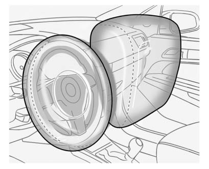
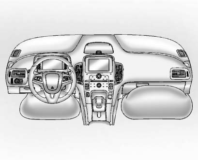
The driver frontal airbag is in the center of the steering wheel.
The front outboard passenger frontal airbag is in the passenger side instrument panel.

The driver knee airbag is below the steering column. The front outboard passenger knee airbag is below the glove box.

Driver Side Shown, Passenger Side Similar
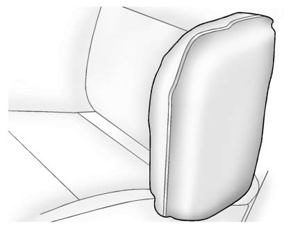
The seat-mounted side impact airbags for the driver and front outboard passenger are in the side of the seatbacks closest to the door.
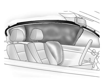
The roof-rail airbags for the driver, right front passenger, and second row outboard passengers are in the ceiling above the side windows.

Rear Seat Driver Side Shown, Passenger Side Similar
On vehicles with second row seatmounted side impact airbags, they are in the sides of the rear seatback closest to the door
WARNING
If something is between an occupant and an airbag, the airbag might not inflate properly or it might force the object into that person causing severe injury or even death. The path of an inflating airbag must be kept clear. Do not put anything between an occupant and an airbag, and do not attach or put anything on the steering wheel hub or on or near any other airbag covering.
Do not use seat accessories that block the inflation path of a seat-mounted side impact airbag.
Never secure anything to the roof of a vehicle with roof-rail airbags by routing a rope or tie‐down through any door or window opening. If you do, the path of an inflating roof-rail airbag will be blocked.
 Airbag System
The vehicle has the following airbags:
• A frontal airbag for the driver.
• A frontal airbag for the front outboard passenger.
• A knee airbag for the driver.
• A knee airbag for the front o ...
 When Should an Airbag Inflate?
This vehicle has advanced technology frontal airbags. Frontal airbags are designed
to inflate in moderate to severe frontal or near frontal crashes to help reduce
the potential for severe injuries ...
Other materials:
Radio(s)
: Press to turn the system on and
off. Turn to increase or decrease the volume.
BAND: Press to choose between FM, AM, or SiriusXM®, if equipped.
MENU/SEL: Turn to select radio stations. Press to select a menu.
: Press to seek the previous station
or track.
: Press to seek the next station
...
Overheated Engine Protection Operating Mode
This emergency operating mode allows the vehicle to be driven to a safe place
in an emergency situation. If an overheated engine condition exists, an overheat
protection mode which alternates firing groups of cylinders helps prevent engine
damage. In this mode, a significant loss in power and ...
Installation Procedure
Cut the front end upper tie bar in corresponding locations to fit the
remaining original panel. The sectioning joint should be trimmed
to allow a gap of one-and-one-half-times the metal thickness at the
sectioning joint.
Create a 50 mm (2 in) backing plate from the unused portion of ...
