Chevrolet Cruze Repair Manual: Metric Fasteners
This vehicle provides fastener dimensions using the metric system. Most metric fasteners are approximate in diameter to equivalent English fasteners. Make replacements using fasteners of the same nominal diameter, thread pitch, and strength.
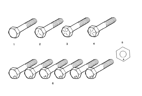
A number marking identifies the OE metric fasteners except cross-recess head screws. The number also indicates the strength of the fastener material. A Posidrive® or Type 1A cross-recess identifies a metric cross-recess screw. For best results, use a Type 1A cross-recess screwdriver, or equivalent, in Posidrive® recess head screws.
GM Engineering Standards and North American Industries have adopted a portion of the ISO-defined standard metric fastener sizes. The purpose was to reduce the number of fastener sizes used while retaining the best thread qualities in each thread size. For example, the metric M6.0 X 1 screw, with nearly the same diameter and 25.4 threads per inch replaced the English 1/4-20 and 1/4-28 screws. The thread pitch is midway between the English coarse and fine thread pitches.
Fastener Strength Identification
- English Bolt, Grade 2 (Strength Class)
- English Bolt, Grade 5 (Strength Class)
- English Bolt, Grade 7 (Strength Class)
- English Bolt, Grade 8 (Strength Class)
- Metric Nut, Strength Class 9
- Metric Bolts, Strength Class Increases as Numbers Increase
The most commonly used metric fastener strength property classes are 9.8 and 10.9. The class identification is embossed on the head of each bolt. The English, inch strength classes range from grade 2 to grade 8. Radial lines are embossed on the head of each bolt in order to identify the strength class. The number of lines on the head of the bolt is 2 lines less than the actual grade. For example, a grade 8 bolt will have 6 radial lines on the bolt head. Some metric nuts are marked with a single digit strength identification number on the nut face.
The correct fasteners are available through GM SPO. Many metric fasteners available in the aftermarket parts channels are designed to metric standards of countries other than the United States, and may exhibit the following:
- Lower strength
- No numbered head marking system
- Wrong thread pitch
The metric fasteners on GM products are designed to new, international standards. The following are the common sizes and pitches, except for special applications:
- M6.0 X 1
- M8 X 1.25
- M10 X 1.5
- M12 X 1.75
- M14 X 2.00
- M16 X 2.00
 Fasteners
Table 1: Metric Prevailing Torque Fastener Minimum Torque Development
Table 2: English Prevailing Torque Fastener Minimum Torque Development ...
 Prevailing Torque Fasteners
Prevailing torque fasteners create a thread interface between the fastener
and the fastener counterpart in order to prevent the fastener
from loosening.
All Metal Prevailing Torque Fasteners
Thes ...
Other materials:
Inflatable Restraint Passenger Presence Detection System - If Equipped
Note: The passenger presence detection system includes an ECU and a
sensor mat that can be serviced separately. After repairing or
replacing any part of the passenger presence detection system, the system must
be rezeroed in order to function properly.
The passenger presence detection system i ...
Front Side Door Window Adjustment
Warning: Refer to Glass and Sheet Metal Handling Warning in the Preface
section.
Warning: Refer to Express Window Down Warning in the Preface section.
Preliminary Procedure
Remove the front side door trim. Refer to Front Side Door Trim
Replacement.
Remove the water deflector. Refe ...
Vehicle Access
Specifications
Door Lock/Indicator Schematics
Door Control Module Schematics
Release Systems Schematics
Fuel Tank Filler Door Lock Actuator Replacement
Preliminary Procedure
Remove the fuel tank filler housing. Refer to Fuel Tank Filler Pipe Housing ...
