Chevrolet Cruze Infotainment System: Navigation Symbols
Following are the most common symbols that appear on a map screen.

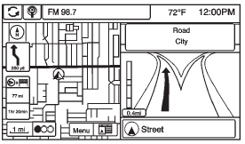
The vehicle symbol indicates the current position and heading direction of the vehicle on the map.
The destination symbol marks the final destination after a route has been planned.
The waypoint symbol marks one or more set waypoints.
A waypoint is a stopover destination point added to the planned route.
The estimated time and distance to the destination are displayed.
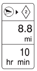
If waypoints have been added to the current route, each waypoint destination displays estimated time and distance.

This symbol indicates that the map view is North up: North up displays North at the top of the map screen regardless of the direction the vehicle is traveling.
Select this screen symbol to change the view to Heading up or 3D.

This symbol indicates that the map view is Heading up.
Heading up view displays the direction the vehicle is traveling at the top of the map screen. The shaded triangle indicates North.
Press this screen symbol to change to 3D mode.
The 3D symbol is the same as the Heading up symbol, but the map is in 3D.

The No GPS symbol appears when there is no Global Positioning System (GPS) satellite signal.

This symbol at the bottom of a map screen changes the current map mode screen.
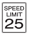
This symbol on the right of the map screen displays the speed limit while on a route. The speed limit may not be accurate due to changes from the Department of Transportation, the local municipalities, or older map data.
Always follow the posted speed limit on the road.
Driving on a Route
Urgent Maneuver Alert
The system will give an indication that the next maneuver is close.
Driving on a Highway
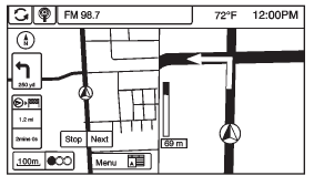
Driving on a Residential Road
 Maps
Maps
This section includes basic information about the map database.
The data is stored in the internal flash memory that is used in the navigation
system.
Detailed Areas
Road network attributes are c ...
 Destination
If route guidance is not active, press the Destination Entry screen button on
the Home Page to access the Destination Entry screen. Several options can be selected
to plan a route by entering de ...
Other materials:
Trailer Towing (Except Fuel Economy Model)
Before pulling a trailer, there are three important considerations that have
to do with weight:
• The weight of the trailer.
• The weight of the trailer tongue.
• The total weight on your vehicle's tires.
Weight of the Trailer
How heavy can a trailer safely be? It should never weigh more ...
Tire Changing
Removing the Spare Tire and Tools
To access the spare tire and tools:
1. Retainer Nut.
2. Tool Bag Tether.
3. Tool Bag.
4. Spare Tire.
1. Open the trunk.
2. Lift the load floor.
3. Turn the retainer nut (1) counterclockwise to remove it.
Then remove the tool bag tether (2) from th ...
Driver or Passenger Seat Side Inflatable Restraint Module Replacement
Warning: Refer to SIR Inflator Module Handling and Storage Warning
in the Preface section.
Warning: Following the deployment of a side impact air bag, inspect the
following parts for damage. Replace these parts if
necessary:
The seat cushion frame
The seat recliner, if equipped
T ...
