Chevrolet Cruze Repair Manual: Waterleak Test Preparation
- GM vehicles are designed to operate under normal environmental conditions.
- The design criteria for sealing materials and components takes into consideration the sealing forces required to withstand the natural elements. These specifications cannot take into consideration any artificial conditions, i.e., high pressure car washes.
- The water leak test procedure has been correlated to the natural elements and will determine the ability of a vehicle to perform under normal operating conditions.
- The first step in diagnosing a leak is determining the conditions under which a leak occurs. If the general leak area can be found, the exact entry point can be isolated using a water hose or an air hose. Some trim panels or components may need to be removed in order to repair the leak.
- If leaks are found around a door, door window, rear compartment lid or liftgate area this does not necessarily indicate a bad weatherstrip. An adjustment to these areas may resolve the condition.
Watertest Stand Assembly

- Pipe (0.5 x 36 in)
- Reducing Tee, Right Stand Only (0.5 x 0.5 x 0.25 in)
- Coupling, Left Stand Only, (0.5 in)
- Tee, Left Stand Only (0.5 in)
- Cross, Right Stand Only (0.5 in)
- Pipe to Hose Nipple, Right Stand Only (0.5 in)
- Female Hose Coupling (5/8 in)
- Input Hose, Right Stand Only (2.0 ft) (5/8 in diameter)
- Close Nipple (0.5 in)
- Cross (0.5 in) with Weld-On Cap (0.5 in)
- Nipple (0.5 x 12 in)
- Cap (0.5 in)
- Female Hose Coupling (5/8 in)
- Cross Hose (12 ft) (5/8 in diameter)
- Hose Quick Connect
- Pipe to Hose Nipple (0.5 in)
- Pipe (0.5 x 60 in)
- Water Pressure Gauge. Right Stand Only
- Full Jet Spray Nozzle, No. 1/2GG-25 or Equivalent
- Coupling (0.5 in)
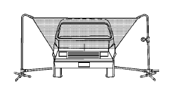
- Assemble the water test stand as shown.

- Position the stands as shown.
The water spray from the stands should overlap the vehicle as shown.
- Have an assistant inside of the vehicle during the test in order to locate any leaks.
- The water pressure at the nozzle should maintain a 155 kPa (22 psi), for at least 4 minutes.

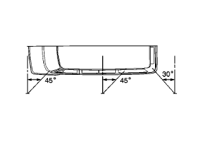
- In order to check the windshield, aim the water spray 30 degrees down and 45 degrees toward the rear.
Aim the water towards the corner of the windshield.
- In order to check the side windows for leaks, position the water stand towards the center of the rear quarter, aiming the water spray 30 degrees down and 45 degrees toward the rear.
- In order to check the back window, aim the water spray 30 degrees down and 30 degrees toward the front.
 Waterleaks
...
 Water Hose Test
Note: Use a water hose without the nozzle attached.
Have an assistant inside of the vehicle i 1. n order to locate the leak.
Begin testing at the base of the window or the windshield.
Slow ...
Other materials:
Aluminum Wheel Porosity Repair
Remove the tire and wheel. Refer to Tire and Wheel Removal
and Installation.
Inflate the tire to the manufactures specified pressure as stated on the
tire.
Submerge the tire/wheel into a water bath in order to locate the leak.
Inscribe a mark on the wheel in order to indic ...
Air Conditioning Compressor and Condenser Hose Replacement (1.6L LDE, LXV,
and 1.8L 2H0)
Removal Procedure
Recover the refrigerant. Refer to Refrigerant Recovery and Recharging
Remove front bumper fascia. Refer to Front Bumper Fascia Replacement
Remove A/C compressor and condenser hose nut (1) from A/C condenser (2).
Remove A/C compressor and condenser hose bol ...
Electrical System Overload
The vehicle has fuses and circuit breakers to protect against an electrical system
overload.
When the current electrical load is too heavy, the circuit breaker opens and
closes, protecting the circuit until the current load returns to normal or the problem
is fixed. This greatly reduces the c ...
