Chevrolet Cruze Repair Manual: Driver or Passenger Seat Replacement
Removal Procedure
Warning: Refer to SIR Warning in the Preface section.
Warning: When carrying a live inflator module, make sure the bag opening is pointed away from you. This minimizes the chance of injury in the case of an accidental deployment. Never carry the inflator module by the wires. Never carry the inflator module by the connector on the underside of the module.
Make sure that the bag and trim cover are facing up whenever you place a live inflator module on any surface. This is necessary to provide a free space for the bag to expand in the unlikely event of accidental deployment. Never rest the steering column assembly on the steering wheel with the inflator module face down, and the column vertical. This may result in personal injury.
- Disable the supplemental inflatable restraint (SIR) system. Refer to SIR Disabling and Enabling.
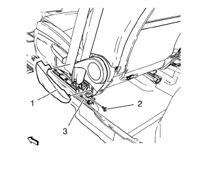
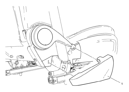
- Remove the front seat outer recliner upper finish cover (1).
- Unscrew the bolt (2)
- Remove the seat belt (3) from the front seat.
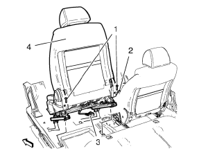
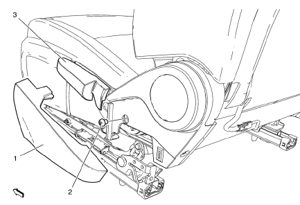
- Unscrew the 2 bolts (1).
- Disconnect the wiring harness plug (2) from the belt buckle.
- Release and disconnect the wiring harness plug (3) front seat.
- Remove the front seat (4) from the guide in front.
Installation Procedure
- Perform the front seat track synchronization. Refer to Front Seat Track Synchronization.
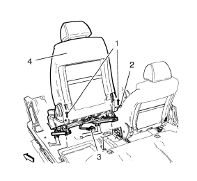
- Install the front seat (4) to the guide in front.
- Connect and latch the wiring harness plug (3) front seat.
- Connect the wiring harness plug (2) from the belt buckle.
Caution: Refer to Fastener Caution in the Preface section.
- Tighten the 2 bolts (1).
Tighten 45 N·m (33 lb in)
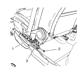
- Install the seat belt (3) to the front seat.
- Tighten the bolt (2).
Tighten 9 N·m (80 lb in)
- Install the front seat outer recliner upper finish cover (1).
- Enable the SIR system. Refer to SIR Disabling and Enabling.
Front Seat Outer Recliner Upper Finish Cover Replacement
- Front Seat Outer Recliner Upper Finish Cover Assembly
Front Seat Adjuster Replacement
- Front Seat Outer Recliner Upper Finish Cover
- Front Seat Adjuster Bolt
Caution: Refer to Fastener Caution in the Preface section.
Tighten 20 N·m(15 lb in)
- Front Seat Adjuster
 Seat Hardware, Trim, and Upholstery
Specifications
...
 Front Seat Track Synchronization
The fore/aft manual adjuster is composed of an inboard track assembly (5),
and outboard track (4) assembly, and an adjuster handle (1).
Each track assembly is made of an upper track (2) and a ...
Other materials:
Towing Equipment
Hitches
Use the correct hitch equipment.
See your dealer or a hitch dealer for assistance.
• The rear bumper on the vehicle is not intended for hitches. Do not attach
rental hitches or other bumper-type hitches to it. Use only a frame-mounted hitch
that does not attach to the bumper.
• ...
Removal Procedure
Warning: Refer to Approved Equipment for Collision Repair Warning in the
Preface section.
Warning: Refer to Glass and Sheet Metal Handling Warning in the Preface section.
Disable the SIR System. Refer to SIR Disabling
and Enabling.
Disconnect the negative battery cable. Refer to Batter ...
Destination
If route guidance is not active, press the Destination Entry screen button on
the Home Page to access the Destination Entry screen. Several options can be selected
to plan a route by entering destinations.
Some destination entry items such as Previous Destinations, Address Book, and
My Home ...
