Chevrolet Cruze Repair Manual: Front Suspension Description and Operation
The front suspension has 2 primary purposes:
- Isolate the driver from irregularities in the road surface.
- Define the ride and handling characteristics of the vehicle.
The front suspension absorbs the impact of the tires travelling over irregular road surfaces and dissipates this energy throughout the suspension system. This process isolates the vehicle occupants from the road surface. The rate at which the suspension dissipates the energy and the amount of energy that is absorbed is how the suspension defines the vehicles ride characteristics. Ride characteristics are designed into the suspension system and are not adjustable. The ride characteristics are mentioned in this description in order to aid in the understanding of the functions of the suspension system. The suspension system must allow for the vertical movement of the tire and wheel assembly as the vehicle travels over irregular road surfaces while maintaining the tire's horizontal relationship to the road.
This requires that the steering knuckle be suspended between a lower control arm and a strut assembly. The lower control arm attaches from the steering knuckle at the outermost point of the control arm. The attachment is through a ball and socket type joint. The innermost end of the control arm attached at 2 points to the vehicle frame through semi-rigid bushings. The upper portion of the steering knuckle is attached to a strut assembly. The strut assembly then connects to the vehicle body by way of an upper bearing. The steering knuckle is allowed to travel up and down independent of the vehicle body structure and frame.
This up and down motion of the steering knuckle as the vehicle travels over bumps is absorbed predominantly by the coil spring. This spring is retained under tension over the strut assembly. A strut is used in conjunction with this system in order to dampen out the oscillations of the coil spring. A strut is a basic hydraulic cylinder. The strut is filled with oil and has a moveable shaft that connects to a piston inside the strut. Valves inside the shock absorber offer resistance to oil flow and consequently inhibit rapid movement of the piston and shaft. Each end of the shock absorber is connected in such a fashion to utilize this recoil action of a spring alone. Each end of the strut is designed as the connection point of the suspension system to the vehicle and acts as the coil spring seat. This allows the strut to utilize the dampening action to reduce the recoil of a spring alone. The lower control arm is allowed to pivot at the vehicle frame in a vertical fashion. The ball joint allows the steering knuckle to maintain the perpendicular relationship to the road surface.
Front suspensions systems utilize a stabilizer shaft. The stabilizer bar connects between the left and right lower control arm assemblies through the stabilizer link and stabilizer shaft insulators. This bar controls the amount of independent movement of the suspension when the vehicle turns. Limiting the independent movement defines the vehicles handling characteristics on turns.
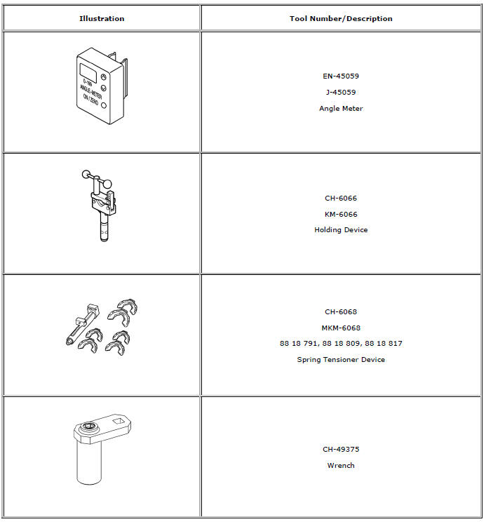
Special Tools and Equipment
 Strut, Strut Component, or Spring Replacement
Special Tools
CH-6068 Spring Tensioner Device
CH-6066 Holding Device
For equivalent regional tools, refer to Special Tools.
Disassembly Procedure
Remove the strut assembly. Refer &n ...
 Rear Suspension
Specifications
Rear Suspension Components
Rear Shock Absorber Upper Mount
Rear Shock Absorber Upper Mount
Rear Shock Absorber Upper Mount
Rear Shock Absorber Upper Mount
Shock Abs ...
Other materials:
Rear Compartment Lid Emblem/Nameplate Replacement (Cruze - Right Side)
Rear Compartment Lid Emblem Assembly
Caution: Refer to Exterior Trim Emblem Removal Caution in the Preface
section.
Procedure
The part and surface should be 21°C (70°F) prior to installation. The
vehicle should remain 21°C (70°F) for
one hour after assembly to allow adhesive to deve ...
Test Probe Caution
Caution: Do not insert test equipment probes (DMM etc.) into any
connector or fuse block terminal. The diameter of the test probes will
deform most terminals. A deformed terminal will cause a poor connection, which
will result in a system failure. Always use the EL-35616
GM-Approved Terminal T ...
Front Fender Replacement
Preliminary Procedure
Remove the front bumper fascia. Refer to Front Bumper Fascia
Replacement
Remove front bumper fascia guide. Refer to Front Bumper Fascia
Replacement
Remove the wheelhouse liner. Refer to Front Wheelhouse Liner Replacement
Remove the headlamp. Refer to H ...
