Chevrolet Cruze Repair Manual: Interior Lamps Dimming
This group includes lamps which may dim. This group may use a combination of vacuum fluorescent illumination, LEDs and incandescent lamps
- HVAC control module, head assembly
- Rear HVAC control module, head assembly
- Radio
- Rear seat audio
- The instrument panel cluster
- The PRNDL lamp, with the exception of the current gear select position
- Power window switches
- Various switches
When the ignition switch is turned to the ON position, the vacuum fluorescent display, radio, turns ON at maximum brightness. When the park lamps are ON, all incandescent back lighting turn ON at the dimming level indicated by the instrument panel cluster dimmer switch.
At the same time all fluorescent display displays dim to match the indicated dimming level. When the headlamp switch is placed in the PARK position, the park lamp supply voltage circuit provides an input to the BCM. The BCM then supplies voltage to the instrument panel cluster dimmer switch through the dimming control circuit. The setting of the instrument panel cluster dimmer switch determines the amount of voltage that the instrument panel cluster dimmer switch supplies to the BCM through the instrument panel cluster dimming lamps low reference circuit. The BCM then sends a PWM voltage to all the interior lamps. All the fluorescent display and incandescent back lighting lamps are provided a specific voltage and are then grounded. When the headlight switch is turned to the park lamp or headlamp position, all incandescent back lighting turn ON at the dimming level indicated by the instrument panel cluster dimmer switch. When the instrument panel cluster dimmer switch is moved from MIN to MAX, all fluorescent display displays, as well as all incandescent back lighting respond from minimum intensity to maximum brightness in response to the instrument panel cluster dimmer switch.
Inadvertent Power
The BCM used in this vehicle controls the lighting system through circuits that enable the interior lamps. The BCM opens these enabling circuits shortly after the ignition switch is turned OFF with no lamp switch activity. If the ignition switch is turned to any position other than OFF, or if a lamp switch is activated during this period, the timer will reset itself.
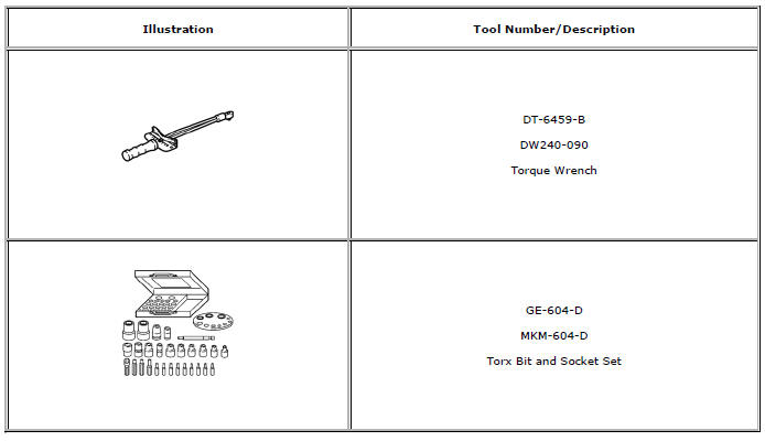
Special Tools and Equipment
 Courtesy/Illuminated Entry Lamps
The following lamps may be manually turned ON by placing the interior lamp
switch in the ON position, or by opening a door while the
switch is in the AUTO position.
The dome lamp
The liftgate ...
 Mirrors
Specifications
Inside Rearview Mirror Schematics
Outside Rearview Mirror Schematics
Outside Rearview Mirror Replacement
Preliminary Procedure
Remove the front side door tri ...
Other materials:
Engine Compartment Overview
1.4L L4 Engine
1. Engine Air Cleaner/Filter
2. Engine Oil Dipstick.
3. Engine Cooling Fan (Out of View).
4. Engine Oil Fill Cap.
5. Remote Negative (-) Grounding Point.
6. Brake/Clutch Fluid Reservoir.
7. Battery
8. Engine Coolant Surge Tank and Pressure Cap.
9. Remote Positive (+ ...
Deployment Outside Vehicle - Steering Wheel Module, Instrument Panel
Module, and Roof Rail Module
Deploy the inflator module outside of the vehicle when the vehicle will be
returned to service. Situations that require deployment outside
of the vehicle include the following:
Using the SIR diagnostics, you determine that the inflator module is
malfunctioning
The inflator module is cosm ...
Cruise Control
For vehicles with cruise control:
: Press to turn the cruise control system on and off.
RES/+: Move the thumbwheel up to resume a previously set speed or to accelerate.
SET/−: Move the thumbwheel down to set a speed or to make the vehicle decelerate.
: Press to disengage cruise contro ...
