
Chevrolet Cruze Repair Manual: Installation Procedure
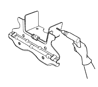
- Create 8 24 mm (5/16 x 15/16 in) slots for MIG-brazing along the edges of the underbody rear side rail reinforcement as noted from the original panel.
- Clean and prepare the attaching surfaces for brazing.
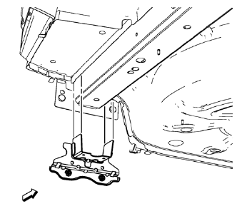
- Position the underbody rear side rail reinforcement on the vehicle.
- Verify the fit of the underbody rear side rail reinforcement.
- Clamp the underbody rear side rail reinforcement into position.
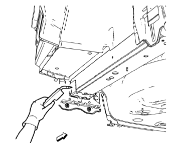
- Braze accordingly.
- Apply the sealers and anti-corrosion materials to the repair area, as necessary. Refer to Anti-Corrosion Treatment and Repair.
- Paint the repaired area. Refer to Basecoat/Clearcoat Paint Systems.
- Install all related panels and components.
- Connect the negative battery cable. Refer to Battery Negative Cable Disconnection and Connection.
- Enable the SIR system. Refer to SIR Disabling and Enabling.
 Removal Procedure
Warning: Refer to Approved Equipment for Collision Repair Warning in the
Preface section.
Warning: Refer to Glass and Sheet Metal Handling Warning in the Preface section.
Disable the SIR Syst ...
 Rear Floor Panel Filler Replacement (MAG-Welding)
Note: According to different corrosion warranties, only the
regional mandatory joining methods are allowed. ...
Other materials:
Remote Keyless Entry (RKE) System
The Remote Keyless Entry (RKE) transmitter may work up to 60m (195 ft) away from
the vehicle.
RKE Transmitter with Remote Start Shown
Press the key release button to extend the key blade. The key can be used for
the ignition and all locks.
Press to unlock the driver door
or all doors.
P ...
Bluetooth
Overview
For vehicles equipped with Bluetooth capability, the system can interact with
many cell phones and devices, allowing:
• Placing and receiving hands-free calls.
• Sharing of the cell phone’s address book or contact list with the vehicle. The
phone book will only display when that phon ...
Steering Wheel Controls
Depending on the vehicle options, some audio functions can be controlled through
the steering wheel controls.
(Push to Talk): Press to interact
with Bluetooth or voice recognition.
(Mute/End Call): Press to decline
an incoming call, or to end a current call. Press to silence the vehicle ...
