
Chevrolet Cruze Repair Manual: Removal Procedure
Warning: Refer to Approved Equipment for Collision Repair Warning in the Preface section.
Warning: Refer to Collision Sectioning Warning in the Preface section.
Warning: Refer to Glass and Sheet Metal Handling Warning in the Preface section.
- Disable the SIR System. Refer to SIR Disabling and Enabling.
- Disconnect the negative battery cable. Refer to Battery Negative Cable Disconnection and Connection.
- Remove all related panels and components.
- Visually inspect the damage. Repair as much of the damage as possible.
- Remove the sealers and anti-corrosion materials from the repair area, as necessary. Refer to Anti-Corrosion Treatment and Repair.
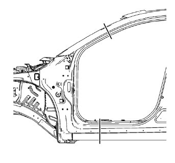
- Create cut lines on the front hinge pillar body.
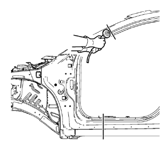
Note: Do not damage any inner panels or reinforcements.
- Cut the panel where sectioning is to be performed.
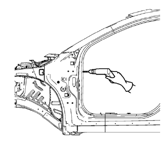
- Locate and mark all the necessary factory welds of the front hinge pillar body.
- Drill all factory welds. Note the number and location of welds for installation of the service assembly
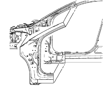
- Remove the damaged front hinge pillar body.
 Front Hinge Pillar Body Sectioning (MIG-Brazing)
Note: According to different corrosion warranties, only the
regional mandatory joining methods are allowed ...
 Installation Procedure
Cut the front hinge pillar body in corresponding locations to fit the
remaining original panel. The sectioning joint should be trimmed
to allow a gap of one-and-one-half-times the metal th ...
Other materials:
Inflatable Restraint Side Impact Sensor Replacement
Warning: Refer to SIR Warning in the Preface section.
Warning: Refer to SIR Inflator Module Handling and Storage Warning in the
Preface section.
Warning: Following the deployment of a side impact air bag, inspect the
following parts for damage. Replace these parts if
necessary:
Th ...
Test Probe Caution
Caution: Do not insert test equipment probes (DMM etc.) into any
connector or fuse block terminal. The diameter of the test probes will
deform most terminals. A deformed terminal will cause a poor connection, which
will result in a system failure. Always use the EL-35616
GM-Approved Terminal T ...
Removal Procedure
Warning: Refer to Approved Equipment for Collision Repair Warning in the
Preface section.
Warning: Refer to Collision Sectioning Warning in the Preface section.
Warning: Refer to Glass and Sheet Metal Handling Warning in the Preface section.
Disable the SIR System. Refer to SIR Disabling ...
