Chevrolet Cruze Repair Manual: Removal Procedure
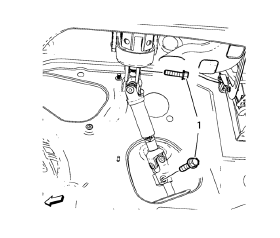
- Support the radiator and condenser from above using the condenser tabs on each side.
- Remove the lower steering intermediate shaft bolt (1).
- Raise the vehicle on a hoist. Refer to Lifting and Jacking the Vehicle.
- Remove the tire and wheel assemblies. Refer to Tire and Wheel Removal and Installation.
- Remove the exhaust flexible pipe. Refer to Exhaust Flexible Pipe Replacement.
- Remove the front compartment splash shield. Refer to Front Compartment Splash Shield Replacement.
- Remove the front compartment insulator, if equipped. Refer to Front Compartment Insulator Replacement.
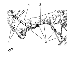
- Remove the wheel speed sensor wiring harness (2) from the frame on both
sides.
Remove the wiring harness retainers (3) from the frame and the lower control arm.
- Remove the radiator wiring harness (1) from the frame.
Remove the wiring harness retainers (4) from the frame.
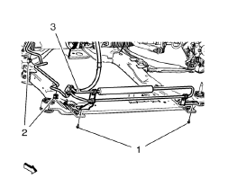
- Remove the power steering fluid cooling pipe bolt (1), clip out (2) and securing the power steering fluid cooling pipe (3) to the vehicle.
- Remove the lower ball joints from the steering knuckles. Refer to Lower Control Arm Replacement.
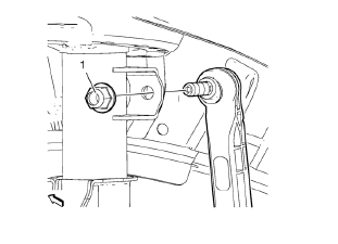
- Remove the stabilizer link nut (1) from the strut.
- Remove the outer tie rods and tie rod nuts from the steering knuckles. Refer to Steering Linkage Outer Tie Rod Replacement.
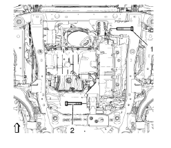
- Remove the front (1) and the rear (2) transmission mount bracket bolts.
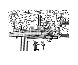
- Raise the CH 904 frame and CH 49289 adapter with the hydraulic jack until it contacts the frame.
- Turn the front wheels to the straight forward position and secure the steering wheel from moving.
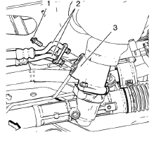
Remove the power steering gear inlet and outlet hose bolts (1). Remove the inlet and outlet hose ( 2) from the steering gear (3).
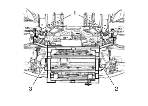
Note: Positioning pins (2, 3) of CH 49289 adapter MUST stick into holes of drivetrain frame.
- Check if wheel alignment is required.
Move out position pins (1) and try to insert into underbody holes.
If guide pins can NOT be inserted, the Wheel Alignment Measurement is required after installation of the drive train frame.
- Loosen the front bumper energy absorber bracket bolt. Refer to Front Bumper Energy Absorber Bracket Replacement.
- Secure the power steering gear to the vehicle.
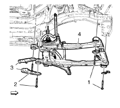
- Remove and discard the frame front bolts (1).
- Remove and discard the frame rear bolts (2).
- Remove the frame reinforcements (3).
- Remove the frame (4) from the vehicle.
- Remove the following components if replacing the frame:
- The lower control arms--Refer to Lower Control Arm Replacement.
- The stabilizer shaft--Refer to Stabilizer Shaft Replacement.
- The radiator support brackets
- The steering gear--Refer to Steering Gear Replacement.
 Drivetrain and Front Suspension Frame Replacement
Special Tools
CH 904 Underframe
CH 49289 Centering Adapter
For equivalent regional tools, refer to Special Tools. ...
 Installation Procedure
Install the following components on the drivetrain and front suspension
frame if removed:
The radiator support brackets.
The stabilizer shaft--Refer to Stabilizer Shaft Replacement.
Th ...
Other materials:
Removal Procedure
Warning: Refer to Approved Equipment for Collision Repair Warning in the
Preface section.
Warning: Refer to Collision Sectioning Warning in the Preface section.
Warning: Refer to Glass and Sheet Metal Handling Warning in the Preface section.
Disable the SIR System. Refer to SIR Disabling ...
Front Side Door Window Adjustment
Warning: Refer to Glass and Sheet Metal Handling Warning in the Preface
section.
Warning: Refer to Express Window Down Warning in the Preface section.
Preliminary Procedure
Remove the front side door trim. Refer to Front Side Door Trim
Replacement.
Remove the water deflector. Refe ...
Fuel Tank Filler Pipe Housing Replacement
Preliminary Procedure
Remove rear wheelhouse panel liner. Refer to Rear Wheelhouse Panel Liner
Replacement.
Remove fuel tank filler door. Refer to Fuel Tank Filler Door
Replacement.
Fuel Tank Filler Door Lock Actuator
Procedure
Disconnect electrical connector.
Fuel Tank ...
