Chevrolet Cruze Repair Manual: Steering Linkage Inner Tie Rod Replacement (Hydraulic Power Steering)
Special Tools
CH-6247 Removal and Installation Tool for the Steering Linkage Inner Tie Rod
For equivalent regional tools, refer to Special Tools.
Removal Procedure
- Raise and support the vehicle. Refer to Lifting and Jacking the Vehicle.
- Remove the tire and wheel assembly. Refer to Tire and Wheel Removal and Installation.
- Remove the steering linkage outer tie rod. Refer to Steering Linkage Outer Tie Rod Replacement.
- Remove the steering gear boot. Refer to Steering Gear Boot Replacement

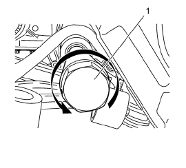
- Remove the steering linkage inner tie rod with CH-6247 remover/installer .
Installation Procedure

- Apply threadlock compound to the threads of the inner tie rod.
Caution: Refer to Fastener Caution in the Preface section.
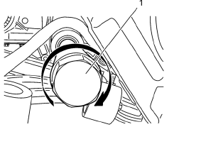
- Install the steering linkage inner rod using the CH-6247 remover/installer and tighten to 90 N·m (64 lb ft).
- Install the steering gear boot. Refer to Steering Gear Boot Replacement.
- Install the steering linkage outer tie rod. Refer to Steering Linkage Outer Tie Rod Replacement.
- Install the tire and wheel assembly. Refer to Tire and Wheel Removal and Installation.
- Measure the wheel alignment. Refer to Wheel Alignment Measurement.
- Adjust front toe. Refer to Wheel Alignment - Steering Wheel Angle and/or Front Toe Adjustment.
- Center the steering angle sensor. Refer to Steering Angle Sensor Centering.
 Steering Gear Replacement (Hydraulic Power Steering)
Special Tools
EN 45059 Torque Angle Sensor Kit
For equivalent regional tools, refer to Special Tools.
Removal Procedure
Turn the front wheels to the straight forward position and secure the
...
 Steering Linkage Inner Tie Rod Replacement (Electronic Power Steering)
Special Tools
CH-6247 Removal and Installation Tool for the Steering Linkage Inner Tie Rod
For equivalent regional tools, refer to Special Tools.
Removal Procedure
Raise and support the vehicle ...
Other materials:
Vehicle Personalization
The audio system controls are used to access the personalization menus for customizing
vehicle features.
CONFIG (Configuration): Press to access the Configuration Settings menu.
MENU/SEL: Press the center of this knob to enter the menus and select
menu items. Turn the knob to scroll through th ...
Installation Procedure
Cut the rear side rail in corresponding locations to fit the remaining
original panel. The sectioning joint should be trimmed to allow a
gap of one-and-one-half-times the metal thickness at the sectioning joint.
Create a 50 mm (2 in) backing plate from the unused portion of the
serv ...
Object Detection System Messages
PARK ASSIST OFF
This message displays when the park assist system has been turned off or when
there is a temporary condition causing the system to be disabled.
SERVICE PARK ASSIST
This message displays if there is a problem with the Ultrasonic Rear Parking
Assist (URPA) system. Do not use thi ...
