Chevrolet Cruze Repair Manual: Inflatable Restraint Steering Wheel Module Coil Centering

Caution: The new SIR coil assembly will be centered. Improper alignment of the SIR coil assembly may damage the unit, causing an inflatable restraint malfunction.
- Verify the following conditions before centering the supplemental inflatable restraint (SIR) steering wheel module coil:
- The wheels on the vehicle are straight ahead.
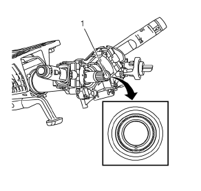
- The centering mark (1) of the steering shaft is in the 6 o'clock position.
- Turn the lobe of the clock spring clockwise until the coil ribbon stops. Do not force.
- Turn the lobe of the clock spring counterclockwise approximately 3 turns to the Neutral position.

- Properly align until the centering window turns yellow (1). This indicates the CENTER position.
Instrument Panel Inflatable Restraint Module Replacement

Warning: Refer to SIR Warning in the Preface section.
Preliminary Procedure
- Disable the SIR system. Refer to SIR Disabling and Enabling.
- Remove the instrument panel assembly. Refer to Instrument Panel Assembly Replacement.
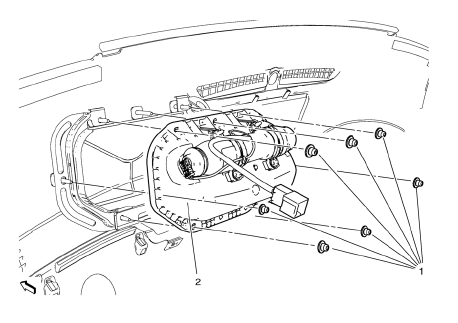
Instrument Panel Inflatable Restraint Module Nut (Qty: 7)
Caution: Refer to Fastener Caution in the Preface section.
Tighten 8 N·m (71 lb in)
Instrument Panel Inflatable Restraint Module Assembly
Tip
Disconnect the electrical connectors.
 Steering Wheel Inflatable Restraint Module Coil Replacement
Preliminary Procedure
Remove the steering column upper trim cover. Refer to Steering Column
Upper Trim Cover Replacement.
Remove the steering column lower trim cover. Refer to Steer ...
 Driver or Passenger Seat Side Inflatable Restraint Module Replacement
Warning: Refer to SIR Inflator Module Handling and Storage Warning
in the Preface section.
Warning: Following the deployment of a side impact air bag, inspect the
following parts for damage ...
Other materials:
Collision Repair
Specifications
Point-to-point measurements are for reference only. All measurements are
given in millimeters. Use these measurements for diagnosing
and estimating. Point-to-point measurements are duplicated with tram bar
pointers set at equal lengths. All die marks, holes, slots, and
fast ...
Fuel Additives
To provide cleaner air, all gasolines in the United States are now required to
contain additives that help prevent engine and fuel system deposits from forming,
allowing the emission control system to work properly. In most cases, nothing should
have to be added to the fuel.
However, some gas ...
Air Conditioning Evaporator Hose Assembly Replacement
Preliminary Procedures
Recover the refrigerant. Refer to Refrigerant Recovery and Recharging.
Remove the headlamp - right side. Refer to Headlamp Replacement.
Loosen power steering fluid reservoir screw.
Remove brake pipes from the dash lower extension panel.
Remove engine mount. Ref ...
