Chevrolet Cruze Repair Manual: Installation Procedure
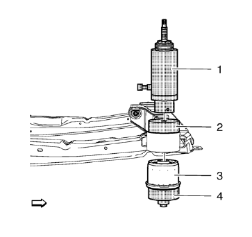
- Install the following components on the drivetrain and front suspension frame:
- CH 49460-1 adapter (2).
- CH 49460-2 adapter (4).
- CH 6615-10 hydraulic cylinder (1).
- NEW frame insulator (3)
Note: Check marking of frame insulator.
- Press carefully the frame insulator in to the front suspension frame, using CH 6616 hand pump .
- Remove the following components from the drivetrain and front suspension frame:
- CH 49460-1 adapter .
- CH 49460-2 adapter .
- CH 6615-10 hydraulic cylinder .
- Install the drivetrain and front suspension frame. Refer to Drivetrain and Front Suspension Frame Replacement.
Front Wheelhouse Liner Replacement
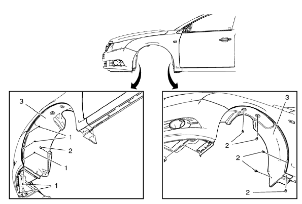
Preliminary Procedure
Remove the tire and wheel assembly. Refer to Tire and Wheel Removal and Installation.
- Front Wheelhouse Liner Screw (Qty: 5)
Caution: Refer to Fastener Caution in the Preface section.
Tighten 2.5 N·m (23 lb in)
- Front Wheelhouse Liner Plastic Retainer (Qty: 7)
- Front Wheelhouse Liner
Rear Wheelhouse Panel Liner Replacement
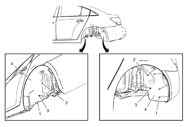
Preliminary Procedure
Remove the tire and wheel assembly. Refer to Tire and Wheel Removal and Installation.
- Rear Wheelhouse Panel Liner Screw (Qty: 4)
Caution: Refer to Fastener Caution in the Preface section.
Tighten 2.5 N·m (23 lb in)
- Rear Wheelhouse Panel Liner Nut (Qty: 2)
Tighten 2.5 N·m (23 lb in)
- Rear Wheelhouse Panel Liner Plastic Retainer (Qty: 2)
- Rear Wheelhouse Panel Liner
Front Fog Lamp Bezel Replacement
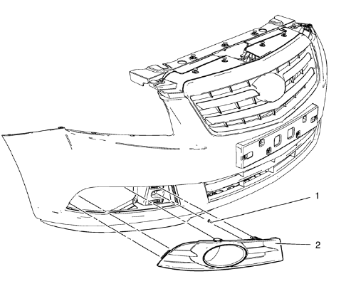
Preliminary Procedure
- Remove front bumper fascia. Refer to Front Bumper Fascia Replacement.
- Remove front fog lamp. Refer to Front Fog Lamp Replacement.
Front Fog Lamp Bezel Screw
Caution: Refer to Fastener Caution in the Preface section.
Tighten 2.5 N·m (23 lb in)
Front Fog Lamp Bezel
Procedure
- Disengage the 4 inner retainer tabs securing the bezel to the front bumper fascia.
- Pull outward from the outer edge in order to release the outer retention clips securing the bezel to the front bumper fascia.
- Remove the front fog lamp bezel.
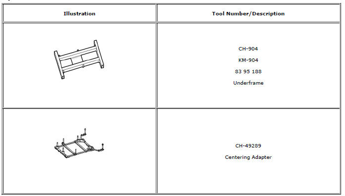
Special Tools and Equipment
 Removal Procedure
Remove the drivetrain and front suspension frame. Refer to Drivetrain
and Front Suspension Frame Replacement.
Mark Installation position of insulator (2) at frame (1).
...

Other materials:
Installation Procedure
Remove all mounds or loose pieces of urethane adhesive from the
pinch-weld area.
Inspect for any of the following problems in order to help prevent
future breakage of the window:
High weld
Solder spots
Hardened sealer
Any other obstruction or irregularity in the pinch-weld fla ...
Installation Procedure
Note: If the location of the original plug weld holes can
not be determined, space the plug weld holes every 40 mm (1½ in).
Drill 8 mm (5/16 in) for plug welding along the edges of the underbody
rear side rail reinforcement as noted from
the original panel.
Clean and ...
Front Side Door Window Weatherstrip Replacement
Preliminary Procedure
Remove the outside rearview mirror. Refer to Outside Rearview
Mirror Replacement.
Remove the front side door window frame rear cover. Refer to Front Side
Door Window Frame Rear Cover Replacement.
Front Side Door Window Weatherstrip
Procedure
Pull the ...
