Chevrolet Cruze Repair Manual: Roof
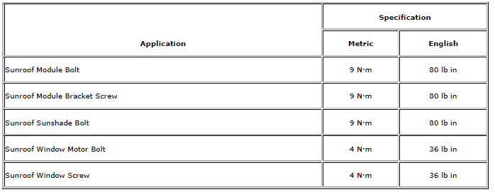
Specifications
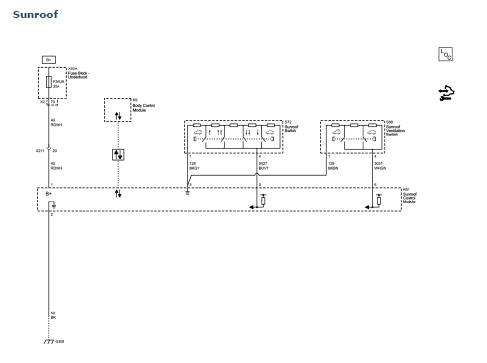
Sunroof Schematics
Sunroof Component Views
- Sunroof Frame
- Sunroof Sunshade
- Sunroof Window
- Sunroof Window Seal
- Sunroof Housing Rear Drain Hose
- Sunroof Housing Drain Gutter
- Sunroof Frame Bolts
- Sunroof Window Guide
- Sunroof Air Deflector Cover
- Sunroof Window Motor
- Sunroof Window Seal
- Sunroof Air Deflector
- Sunroof Housing Front Drain Hose
- Sunroof Window Bolts
Sunroof Air Deflector Replacement
Sunroof Air Deflector
Tip
Cycle the sunshade window to the full rearward position.
Sunroof Air Deflector Cover Replacement
Sunroof Air Deflector Cover
Procedure
- Cycle the sunshade window to the vent position.
- Unclip the sunroof air deflector cover out of the guide.
Sunroof Frame Replacement
Preliminary Procedure
- Remove the headlining trim panel. Refer to Headlining Trim Panel Replacement.
- Remove the sunroof window. Refer to Sunroof Window Replacement.
- Remove the sunroof air deflector cover. Refer to Sunroof Air Deflector Cover Replacement.
- Remove the sunroof sunshade. Refer to Sunroof Sunshade Replacement.
- Remove the sunroof window motor. Refer to Sunroof Window Motor Replacement.
Sunroof Module Bolt (Qty: 12)
Caution: Refer to Fastener Caution in the Preface section.
Tighten 9 N·m (80 lb in)
Sunroof Frame
Procedure
With the aid of an assistant, lower the sunroof frame and remove the sunroof frame out through the passenger side door.
Sunroof Housing Drain Gutter Replacement
Preliminary Procedure
- Remove the sunroof module assembly. Refer to Sunroof Module Assembly Replacement.
- Cycle the sunroof window to the vent position.
Sunroof Housing Drain Gutter
Tip
Clip the sunroof housing drain gutter out from guide.
Sunroof Housing Front Drain Hose Replacement
Preliminary Procedure
- It is only necessary to lower the headliner. Only perform the steps in the headliner replacement procedure that will lower the headliner enough to gain access to the part. Refer to Headlining Trim Panel Replacement.
- Remove the front wheelhouse liner. Refer to Front Wheelhouse Liner Replacement.
Sunroof Housing Front Drain Hose
Procedure
Disengage the sunroof drain hose from the attachment points on the windshield pillar.
Sunroof Housing Rear Drain Hose Replacement
Preliminary Procedure
- It is only necessary to lower the headliner. Only perform the steps in the headliner replacement procedure that will lower the headliner enough to gain access to the part. Refer to Headlining Trim Panel Replacement.
- Remove the rear bumper fascia. Refer to Rear Bumper Fascia Replacement.
- Remove the body side trim panel left side. Refer to Body Side Trim Panel Replacement - Left Side.
- Remove the body side trim panel right side. Refer to Body Side Trim Panel Replacement - Right Side.
Sunroof Housing Rear Drain Hose
Procedure
Disengage the sunroof drain hose from the attachment clips on the roof rail, the C-pillar, and the rear compartment.
Sunroof Module Assembly Replacement
Preliminary Procedure
Remove the headlining trim panel. Refer to Headlining Trim Panel Replacement.
- Sunroof Module Bolt (Qty: 12)
Caution: Refer to Fastener Caution in the Preface section.
Tighten 9 N·m (80 lb in)
- Sunroof Module Assembly
Note: A new sunroof module assembly does not include the sunroof window, the motor, the sunshade, or the finishing lace as components. You must install the old components to the new sunroof module assembly.
Sunroof Window Motor Replacement
Preliminary Procedure
It is only necessary to lower the headliner. Only perform the steps in the headliner replacement procedure that will lower the headliner enough to gain access to the part. Refer to Headlining Trim Panel Replacement.
- Sunroof Window Motor Bolt (Qty: 3)
Caution: Refer to Fastener Caution in the Preface section.
Tighten 4 N·m (36 lb in)
- Sunroof Window Motor Assembly
Tip
Disconnect the electrical connector.
Sunroof Sunshade Replacement
Preliminary Procedure
- Remove the headliner. Refer to Headlining Trim Panel Replacement.
- It is only necessary to lower the sunroof module assembly. Only perform the steps in the sunroof module assembly replacement procedure that will lower the sunroof module assembly enough to gain access to the sunroof module bracket screws. Refer to Sunroof Module Assembly Replacement.
- Sunroof Module Bracket Screw (Qty: 2)
Caution: Refer to Fastener Caution in the Preface section.
Tighten 9 N·m (80 lb in)
- Sunroof Sunshade
Procedure
Push the sunshade assembly down to release from sunshade guide.
Sunroof Window Seal Replacement
Preliminary Procedure
Remove the sunroof window. Refer to Sunroof Window Replacement.
- Sunroof Window Seal
Procedure
Wipe the perimeter of the frame area with a clean cloth.
Note: Ensure that the seal is properly seated around the entire perimeter of the window frame.
Sunroof Window Seal Replacement - Front
Preliminary Procedure
Open the sunroof until it's in full opening position.
- Sunroof Window Seal - Front
Sunroof Switch Replacement
Preliminary Procedure
Remove the roof console. Refer to Roof Console Replacement.
Sunroof Switch
Procedure
- Unsnap the switch from the console.
- Disconnect the electrical connector.
Sunroof Window Replacement
Preliminary Procedure
Remove the sunroof air deflector cover. Refer to Sunroof Air Deflector Cover Replacement.
- Sunroof Window Bolt (Qty: 4)
Caution: Refer to Fastener Caution in the Preface section.
Tighten 4 N·m (36 lb in)
- Sunroof Window
Procedure
Adjust the sunroof window after installation
Sunroof Description and Operation
The tilt/slide sunroof consists of a moving glass panel and a manual sunshade. In the tilt/slide sunroof system the rear of the glass tilts up for venting and slides between the head liner and roof panel as it slides open. The glass is controlled by an integrated motor/controller.
The sunshade has a mechanical connection to the glass causing it to open with the glass and keeping it from closing more than the glass.
The electrical portion of the tilt/slide sunroof system consists of:
- Body control module (BCM)
- Sunroof glass control module
- Sunroof control switch assembly
- Vent control switch assembly
- Local interconnected network (LIN-Bus)
The sunroof electrical system uses a master/slave configuration utilizing a LIN-Bus based system for communication. The BCM is designated as the master, while the sunroof control module is configured as the slave.
As the system master, the BCM uses the LIN-Bus communication bus to enable or disable sunroof operation, communicate vehicle information to the sunroof controller, and request sunroof movement. The sunroof controller provides system status and diagnostic information to the BCM for diagnostic reporting and operational purposes.
The sunroof glass is controlled by a integrated motor/controller containing the necessary electronics, motor, hall effect position sensors, as well as the interface to the driver control switches. The motor/controller is capable of controlling motion based on control switch activation and LIN-Bus message commands from the system master.
The operational calibrations for the sunroof integrated motor/controller are loaded over the LIN-Bus communication bus by the sunroof system master, the BCM.
Sunroof Glass and Sunshade Control Switches
The sunroof control switches are connected directly to the controller. The sliding glass switches provide detent positions for open, express open, off, close, and express close. The vent switches provide detent positions for open, off, and close. The control switch completes the circuit between two signals provided by the control module, a reference ground input and a pull-up voltage provided by an analog to digital switch input. The control switches place a different resistor ladder network in the circuit depending on the function selected. The controller’s analog to digital switch input reads the resulting voltage range and determines the function as indicated in the included charts.
System Protection Functions
Normal operation of the sunroof system may be altered by one of the following events.
Obstacle or Blockage Detection
When enabled, obstacle detection is active only while the sunroof opening is approximately 4-200 mm (0.16-7.87 in) when moving in the closing direction. When an obstacle is detected in this range, the motion in the closing direction will stop and the sunroof will reverse direction for a short distance. The reversal shall complete regardless of operating Mode. If the travel is outside the range defined above, the sunroof will try to continue closing until it detects a motor stall condition or the system is at one of it’s defined stops.
Motor Stall
If the sunroof is moving in the open or close direction and stops moving for 350 ms while the switch or LIN-Bus command is active, and no obstacle has been detected, the motor shall be turned off to prevent overheating.
Sunroof System Thermal Protection
The sunroof controllers have a thermal protection algorithm to protect the sunroof controller and motor from damage due to overheating conditions resulting from immoderately switch actuations. The thermal protection algorithm will cause any new sunroof open commands to be ignored until the motor is allowed to cool. A number of close requests during an over temperature condition will be allowed. If the thermal protection is triggered during an obstacle detection event, the sunroof reversal shall be finished
Sunroof Operation
Vent - Open to Vent Position
When the sunroof is closed or in a partial vent position and the sunroof vent open switch becomes active, the sunroof shall begin to 'Express open' to the vent position. sunroof motion shall cease when the Sunroof reaches the vent position or if the sunroof sliding glass switch becomes active.
Vent - Close from Vent
When the sunroof is in the vent position and the sunroof vent switch enters the 'Close' state, the sunroof will begin to express close the sunroof. Motion will continue until the sunroof has reached its fully closed position or if the sunroof sliding glass switch becomes active.
Sliding Class - Normal Open (Non-Express)
When the sunroof is not in a vent position and the sunroof sliding glass switch is held in the 'Open' position, the sunroof will begin opening.
Motion will continue until the switch returns to the 'Off' state or the vent switch transitions to any active state.
Sliding Class - Sunroof Express Open
When the sunroof control switch transitions to the 'Express Open' state and the sunroof is not in a vent position, the sunroof will express open until the controller determines the sunroof has reached the comfort stop position or the fully 'Open' position, the switch transitions to another state after first returning to the ‘Off’ position, or the vent switch transitions to an active state.
Sliding Class - Normal Close (Non-Express)
When the sunroof switch is in the 'Close' state and the sunroof is not in the vent position, the controller will begin moving the sunroof in the close direction. If the vent switch becomes active the motor will be turned off.
Sliding Class - Sunroof Express Close
When the sunroof switch is in the 'Express Close' state and the sunroof is not in a vent position, the sunroof will express close until the controller determines the sunroof has reached the fully closed position, or the switch transitions to another state after first returning to the ‘Off ’ position. The sunroof motion will cease if the switch transitions back to the ‘Close’ or ‘Express Close’ state after returning to the ‘Off ’ position first or the vent switch transitions to any active state.
Water Management Description and Operation
Any water that passes the roof seal is drained from the sunroof tray by 2 tubes in the front (1) and 2 tubes in the back (2) of the sunroof module assembly that lead from the corners of the tray to the rocker panels of the vehicle. The tray which acts as a framework for the sunroof assembly, has a water channel that encircles the sunroof opening and directs the water to the drain tubes.
In the graphic below the arrows show the water flow direction in the tray which acts as a framework for the sunroof assembly and drains system.
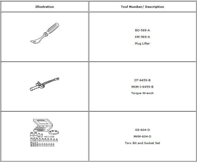
Special Tools and Equipment
 Wiper/Washer System Description and Operation
Wiper/Washer System Components
The wiper/washer system consists of the following electrical components:
Windshield Wiper Relay
Windshield Wiper Speed Control Relay
Windshield Washer Pump Rela ...
 Seatbelts
Specifications
Seat Belt Schematics
...
Other materials:
Antilock Brake System (ABS) Warning Light
The Antilock Brake System (ABS) light comes on briefly when the engine is started.
If the light does not come on, have it fixed so it will be ready to warn if there
is a problem.
If the ABS light comes on and stays on while driving, stop as soon as possible
and turn the ignition off.
Start ...
Installation Procedure
Cut the front hinge pillar body in corresponding locations to fit the
remaining original panel. The sectioning joint should be trimmed
to allow a gap of one-and-one-half-times the metal thickness at the
sectioning joint.
Create a 50 mm (2 in) backing plate from the unused portion of ...
Water Management Description and Operation
Plenum Water Flow Direction and Cleaning
A large percentage of water will flow off the windshield area into the plenum
chamber drain system and then down the outside on the
plenum to the underside of the vehicle. To ensure that the plenum chamber water
management system performs properly, the ...
