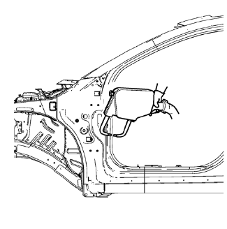
Chevrolet Cruze Repair Manual: Installation Procedure
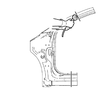
- Cut the front hinge pillar body in corresponding locations to fit the remaining original panel. The sectioning joint should be trimmed to allow a gap of one-and-one-half-times the metal thickness at the sectioning joint.
- Create a 50 mm (2 in) backing plate from the unused portion of the service part.
- Create 5 x 18 mm (4/16 x 11/16 in) slots for MIG-brazing along the sectioning cut on the remaining original part. Locate these holes 13 mm (1/2 in) from the edge of part and spaced 40 mm (1½ in) apart.
- Prepare all mating surfaces as necessary.
- Fit the backing plates halfway into the sectioning joints, clamp in place and braze to the vehicle.
- Align the front hinge pillar body.
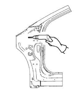
- Create 6 x 20 mm (4/16 x 12/16 in) slots for MIG-brazing in locations where you can not apply a resistance spot welder.
- Clean and prepare the attaching surfaces for brazing.
Note: In MIG-brazing areas 50 mm (2 in) must be kept clear of structural adhesive.
- Apply structural adhesive to all attaching surfaces.
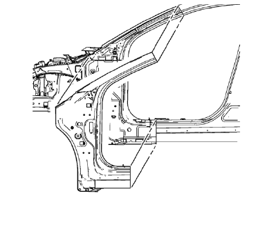
- Position the front hinge pillar body on the vehicle.
- Verify the fit of the front hinge pillar body.
- Clamp the front hinge pillar body into position.
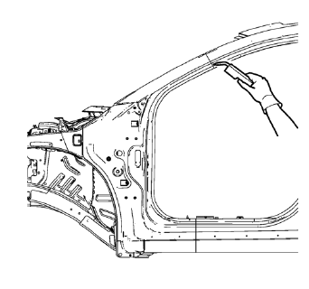
- Plug weld accordingly.
- Spot weld accordingly.
- To create a solid braze with minimum heat distortion, make 25 mm (1 in) stitch brazes along the seam with 25 mm (1 in) gaps between them. Then go back and complete the stitch braze.
- Apply the sealers and anti-corrosion materials to the repair area, as necessary. Refer to Anti-Corrosion Treatment and Repair.
- Paint the repaired area. Refer to Basecoat/Clearcoat Paint Systems.
- Install all related panels and components.
- Connect the negative battery cable. Refer to Battery Negative Cable Disconnection and Connection.
- Enable the SIR system. Refer to SIR Disabling and Enabling.
 Removal Procedure
Warning: Refer to Approved Equipment for Collision Repair Warning in the
Preface section.
Warning: Refer to Collision Sectioning Warning in the Preface section.
Warning: Refer to Glass and She ...
 Body Hinge Pillar Lower Reinforcement Replacement (MAG-Welding)
Note: According to different corrosion warranties, only the
regional mandatory joining methods are allowed. ...
Other materials:
Brakes
This vehicle has front disc brakes and could have rear drum brakes or rear disc
brakes.
Disc brake pads have built-in wear indicators that make a high-pitched warning
sound when the brake pads are worn and new pads are needed.
The sound can come and go or be heard all the time the vehicle is m ...
Front Floor Console Storage Tray Replacement
Preliminary Procedure
Remove the automatic or manual transmission control lever trim cover. Refer
to Automatic or Manual Transmission Control Lever
Trim Cover Replacement
Front Floor Console Storage Tray Screw (Qty: 2)
Caution: Refer to Fastener Caution in the Preface section.
Tighte ...
Jump Starting
If the battery has run down, try to use another vehicle and some jumper cables to start your vehicle.
Be sure to use the following steps to do it safely.
WARNING
Batteries can hurt you. They can be dangerous because:
• They contain acid that can burn you.
• They contain gas ...
