Chevrolet Cruze Repair Manual: Installation Procedure
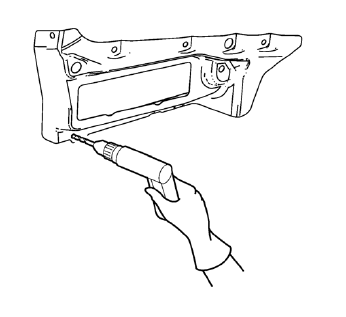
- Drill 8 mm (5/16 in) for plug welding along the edges of the body side outer lower panel as noted from the original panel.
Note: If the location of the original plug weld holes can not be determined, space the plug weld holes every 40 mm (1½ in).
- Clean and prepare the attaching surfaces for welding.
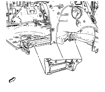
- Position the body side outer lower panel on the vehicle.
- Verify the fit of the body side outer lower panel.
- Clamp the body side outer lower panel into position.
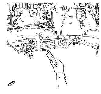
- Plug weld accordingly.
- Apply the sealers and anti-corrosion materials to the repair area, as necessary. Refer to Anti-Corrosion Treatment and Repair.
- Paint the repaired area. Refer to Basecoat/Clearcoat Paint Systems.
- Install all related panels and components.
- Connect the negative battery cable. Refer to Battery Negative Cable Disconnection and Connection.
- Enable the SIR system. Refer to SIR Disabling and Enabling.
 Removal Procedure
Warning: Refer to Approved Equipment for Collision Repair Warning in the
Preface section.
Warning: Refer to Glass and Sheet Metal Handling Warning in the Preface section.
Disable the SIR Syst ...
 Body Side Outer Lower Panel Replacement (MIG-Brazing)
Note: According to different corrosion warranties, only the
regional mandatory joining methods are allowed. ...
Other materials:
Refrigerant Recovery and Recharging
Special Tools
GE-45037 A/C Oil Injector
For equivalent regional tools, refer to Special Tools.
Refrigerant Recovery and Recharging
Warning: To prevent personal injury, avoid breathing A/C Refrigerant
and lubricant vapor or mist. Work in a well ventilated area. To
remove refrigerant from the A ...
When Should an Airbag Inflate?
This vehicle has advanced technology frontal airbags. Frontal airbags are designed
to inflate in moderate to severe frontal or near frontal crashes to help reduce
the potential for severe injuries, mainly to the driver's or front outboard passenger's
head and chest.
However, they are ...
Uniform Tire Quality Grading
Quality grades can be found where applicable on the tire sidewall between tread
shoulder and maximum section width. For example:
Treadwear 200 Traction AA Temperature A
The following information relates to the system developed by the United States
National Highway Traffic Safety Administration ...
