Chevrolet Cruze Repair Manual: Seat Heating and Cooling
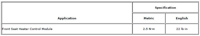
Specifications
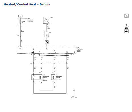
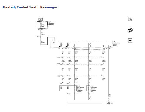
Heated/Cooled Seat Schematics
Front Seat Heater Control Module Replacement
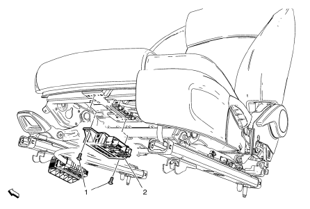
Preliminary Procedure
Driver or passenger seat replacement. Refer to Driver or Passenger Seat Replacement.
Front Seat Heater Control Module Bolt (Qty: 2)
Caution: Refer to Fastener Caution in the Preface section.
Tighten 2.5 N·m (23 lb in)
Front Seat Heater Control Module
Procedure
Disconnect the electrical connector.
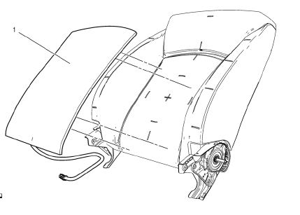
Driver or Passenger Seat Back Cushion Heater Replacement
Preliminary Procedure
Front seat back cushion cover and cushion pad replacement. Refer to Front Seat Back Cushion Cover and Cushion Pad Replacement
- Front Seat Back Heater
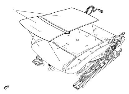
Driver Seat Cushion Heater Replacement
Preliminary Procedure
Front seat cushion cover and pad replacement. Refer to Front Seat Cushion Cover and Pad Replacement.
- Front Seat Heater
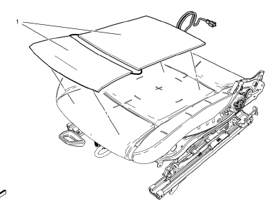
Passenger Seat Cushion Heater Replacement
Preliminary Procedure
Front seat cushion cover and pad replacement. Refer to Front Seat Cushion Cover and Pad Replacement.
Front Seat Heater
Heated Seats Description and Operation
Heated Seat Components
The driver and passenger heated seats consist of the following components:
- Left heated seat switch
- Right heated seat switch
- HVAC control
- Seat heating control module
- Driver seat cushion heating element
- Driver seat back heating element
- Driver seat cushion temperature sensor
- Passenger seat cushion heating element
- Passenger seat back heating element
- Passenger seat cushion temperature sensor
Power and Ground
Battery positive voltage is supplied at all times to the seat heating control module through a 30 A fuse located in the underhood fuse block.
This voltage is used by the module to supply power to the seat heating elements. Ground for the module is provided at G307.
Heated Seat Operation
The driver and passenger heated seats are controlled by a single seat heating control module that is located under the driver seat cushion.
Both heated seats are controlled by separate heated seat switches that are located in the HVAC control. When a heated seat switch is pressed, a serial data message is sent from the HVAC control to the HVAC control module indicating the heated seat command. The HVAC control module then serves as a gateway to transmit the message to the seat heating control module via the serial data line. In response to this signal, the seat heating control module applies battery positive voltage through the element supply voltage circuit to the appropriate seat heating elements. The seat heating control module then sends a serial data message back to the HVAC control module to gateway the information to the HVAC control to either illuminate or turn off the appropriate temperature indicator.
Temperature Regulation
When the engine ON, the heated seats will initialize in the OFF state. With each activation of the heated seat switch, the seat heating control module will cycle the temperature setting in the following manner: HIGH, MEDIUM, LOW, and OFF.
The seat heating control module monitors the seat temperature through the temperature sensor signal circuit and the temperature sensor (thermistor) that is located in the seat cushion. The temperature sensor is a variable resistor, it's resistance changes as the temperature of the seat changes. When the temperature sensor resistance indicates to the seat heating control module that the seat has reached the desired temperature, the module opens the ground path of the seat heating elements through the heated seat element control circuit. The module will then cycle the element control circuit open and closed in order to maintain the desired temperature.
Load Management
electrical power management function is designed to monitor the vehicle electrical load and determine when the battery is potentially in a high discharge condition. The heated seat system is one of the vehicle loads that is subject to reduction during a battery discharge condition. For more information on load management refer to Electrical Power Management Description and Operation.
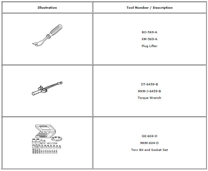
Special Tools and Equipment
 Thread Repair
General purpose thread repair kits are available commercially.
Warning: Refer to Safety Glasses Warning in the Preface section.
Note: Refer to the thread repair kit manufacturer's instructions
...
 Restraints
Specifications
Module Power, Ground, and MIL
Front Impact Sensor, Retractors, and Driver/Passenger Air
Bags
Side Impact Sensors and Side/Roof Air Bags
Air Bag Indicator and Disab ...
Other materials:
Removal Procedure
Warning: Refer to Approved Equipment for Collision Repair Warning in the
Preface section.
Warning: Refer to Collision Sectioning Warning in the Preface section.
Warning: Refer to Glass and Sheet Metal Handling Warning in the Preface section.
Disable the SIR System. Refer to SIR Dis ...
Overview
1.
• Turns the system on or off and adjusts the volume.
2. Buttons 1 to 6
• Radio: Saves and selects favorite stations.
3.
• Radio: Seeks the previous station.
• CD: Selects the previous track or rewinds within a track.
4.
• CD: Pauses playback, and stops playback.
5.
• Radio: ...
California Fuel Requirements
If the vehicle is certified to meet California Emissions Standards, it is designed
to operate on fuels that meet California specifications. See the underhood emission
control label. If this fuel is not available in states adopting California Emissions
Standards, the vehicle will operate satisf ...
