Chevrolet Cruze Repair Manual: Steering Column Replacement (Right Hand Drive)
Caution: With wheels of the vehicle facing straight ahead, secure the steering wheel utilizing steering column anti-rotation pin, steering column lock, or a strap to prevent rotation. Locking of the steering column will prevent damage and a possible malfunction of the SIR system. The steering wheel must be secured in position before disconnecting the following components:
- The steering column
- The steering shaft coupling
- The intermediate shaft(s)
After disconnecting these components, do not rotate the steering wheel or move the front tires and wheels. Failure to follow this procedure may cause the SIR coil assembly to become un-centered and cause possible damage to the SIR coil. If you think the SIR coil has became un-centered, refer to your specific SIR coil’s centering procedure to re-center SIR Coil.
Caution: Once the steering column is removed from the car, the column is extremely susceptible to damage. Dropping the column on its end could collapse the steering shaft or loosen the plastic injections which maintain column rigidity. Leaning on the column could cause the jacket to bend or deform. Any of the above damage could impair the column's collapsible design. If it is necessary to remove the steering wheel, use only the specified steering wheel puller. Under no conditions should the end of the shaft be hammered upon as hammering could loosen plastic injections which maintain column rigidity.
Removal Procedure
- Remove the instrument panel lower trim pad cover. Refer to Instrument Panel Lower Trim Panel Replacement - Left Side.
- Remove the intermediate steering shaft. Refer to Intermediate Steering Shaft Replacement.
- Remove the steering wheel. Refer to Steering Wheel Replacement.
- Remove the steering column upper trim cover. Refer to Steering Column Upper Trim Cover Replacement.
- Remove the steering column lower trim cover. Refer to Steering Column Lower Trim Cover Replacement.
- Disconnect any electrical connectors as needed.
Note: Install tie straps between the tilt lever bracket and the base of the steering column to prevent the steering column jacket from pulling apart. The tilt lever MUST be in the LOCK (FULL UP) position during the steering column removal and installation to ensure that the tilt lever bracket remains rigid. Also install tie straps around the tilt lever and the steering column jacket to keep the tilt lever in the LOCK position. Do not bend the steering column energy absorbing straps located on the upper steering column mounting bracket.
- Install tie straps as described above
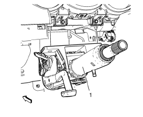
- Remove the steering column nuts (1).
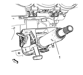
- Remove the steering column.
Installation Procedure
Note: Start all nuts by hand before finalizing any torques.
Note: Do not bend the steering column energy absorbing straps located on the upper steering column mounting bracket during installation.
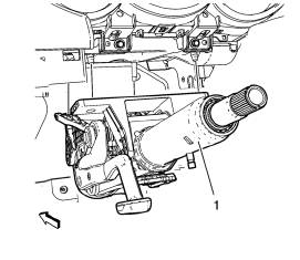
- Install the steering column.
Caution: Refer to Fastener Caution in the Preface section.
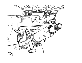
- Install the steering column nuts (1). Tighten the steering column nuts 22 N·m (16 lb ft)+ 45°.
Warning: In order to ensure the intended function of the steering column in a vehicle during a crash and in order to avoid personal injury to the driver, perform the following:
- Tighten the steering column lower fasteners before you tighten the steering column upper fasteners. Failure to do this can damage the steering column.
- Tighten the steering column fasteners to the specified torque. Overtightening the upper steering column fasteners could affect the steering column collapse.
- Remove the tie straps.
- Connect any electrical connectors as needed.
- Install the steering column lower trim cover. Refer to Steering Column Lower Trim Cover Replacement.
- Install the steering column upper trim cover. Refer to Steering Column Upper Trim Cover Replacement.
- Install the steering wheel. Refer to Steering Wheel Replacement.
- Install the intermediate steering shaft. Refer to Intermediate Steering Shaft Replacement.
- Install the instrument panel lower trim pad cover. Refer to Instrument Panel Lower Trim Panel Replacement - Left Side.
- Calibrate the steering angle sensor. Refer to Power Steering Control Module Calibration.
Steering Angle Sensor Replacement
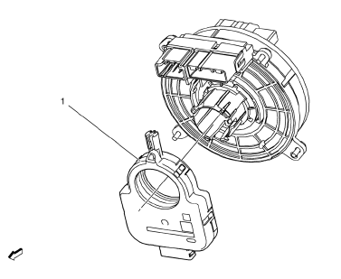
Preliminary Procedure
Remove the steering wheel inflatable restraint module coil. Refer to Steering Wheel Inflatable Restraint Module Coil Replacement.
Steering Wheel Position Sensor
Warning: Never rotate the steering angle sensor. Rotating the steering angle sensor could limit the operation of the electronic power steering (EPS) system, and result in personal injury.
Procedure
- Press in the clip on the inflatable restraint steering wheel module clock-spring coil to remove the sensor.
- Calibrate the steering angle sensor. Refer to Power Steering Control Module Calibration.
 Turn Signal Switch Replacement
Preliminary Procedure
Remove the steering column upper trim cover. Refer to Steering Column
Upper Trim Cover Replacement.
Remove the steering column lower trim cover. Refer to Steer ...
 Steering Wheel and Column Description and Operation
The steering wheel and column has 4 primary functions:
Vehicle steering
Vehicle security
Driver convenience
Driver safety
Vehicle Steering
The steering wheel is the first link between th ...
Other materials:
Installation Procedure
Clean and prepare the attaching surfaces for welding.
Position the roof rear header panel (1) on the vehicle.
Verify the fit of the panel.
Clamp the roof rear header panel into position.
Spot weld accordingly as noted from the original panel.
Apply the sealer ...
Halogen Bulb Warning
Warning: Halogen bulbs contain gas under pressure. Handling a bulb
improperly could cause it to shatter into flying glass fragments. To
help avoid personal injury:
Turn off the lamp switch and allow the bulb to cool before changing
the bulb.
Leave the lamp switch OFF until the bulb chang ...
Air/Wind Noise
Special Tools
CH-39570 Chassis Ear
GE-41416 Ultrasonic Leak Detector
Warning: Refer to Assistant Driving Warning in the Preface section.
To analyze a reported windnoise condition, test drive the vehicle to
determine the origin of the noise.
Choose a regular route with smooth and strai ...
