Chevrolet Cruze Repair Manual: Heating and Air Conditioning System Description and Operation
Engine Coolant
Engine coolant is the key element of the heating system. The thermostat controls engine operating coolant temperature. The thermostat also creates a restriction for the cooling system that promotes a positive coolant flow and helps prevent cavitation. Coolant enters the heater core through the inlet heater hose, in a pressurized state.
The heater core is located inside the HVAC module. The heat of the coolant flowing through the heater core is absorbed by the ambient air drawn through the HVAC module. Heated air is distributed to the passenger compartment, through the HVAC module, for passenger comfort.
The amount of heat delivered to the passenger compartment is controlled by opening or closing the HVAC module air temperature door.
The coolant exits the heater core through the return heater hose and recirculated back through the engine cooling system.
A/C Cycle
Refrigerant is the key element in an air conditioning system. R-134a is presently the only EPA approved refrigerant for automotive use.
R-134a is an very low temperature gas that can transfer the undesirable heat and moisture from the passenger compartment to the outside air.
The A/C compressor is belt driven and operates when the magnetic clutch is engaged. The compressor builds pressure on the vapor refrigerant. Compressing the refrigerant also adds heat to the refrigerant. The refrigerant is discharged from the compressor, through the discharge hose, and forced to flow to the condenser and then through the balance of the A/C system. The A/C system is mechanically protected with the use of a high pressure relief valve. If the high pressure switch were to fail or if the refrigerant system becomes restricted and refrigerant pressure continued to rise, the high pressure relief will pop open and release refrigerant from the system.
Compressed refrigerant enters the condenser in a high temperature, high pressure vapor state. As the refrigerant flows through the condenser, the heat of the refrigerant is transferred to the ambient air passing through the condenser. Cooling the refrigerant causes the refrigerant to condense and change from a vapor to a liquid state.
The condenser is located in front of the radiator for maximum heat transfer. The condenser is made of aluminum and aluminum cooling fins, which allows rapid heat transfer for the refrigerant. The semi-cooled liquid refrigerant exits the condenser and flows through the liquid line, to the thermal expansion valve.
The thermal expansion valve is located in the liquid line between the condenser and the evaporator. The thermal expansion valve is the dividing point for the high and the low pressure sides of the A/C system. As the refrigerant passes through the thermal expansion valve, the pressure of the refrigerant is lowered. Due to the pressure differential of the liquid refrigerant, the refrigerant will begin to vaporize at the thermal expansion valve. The thermal expansion valve also meters the amount of liquid refrigerant that can flow into the evaporator.
Refrigerant exiting the thermal expansion valve flows into the evaporator core in a low pressure, liquid state. Ambient air is drawn through the HVAC module and passes through the evaporator core. Warm and moist air will cause the liquid refrigerant boil inside of the evaporator core. The boiling refrigerant absorbs heat from the ambient air and draws moisture onto the evaporator. The refrigerant exits the evaporator back through the thermal expansion valve and into the suction line and back to the compressor, in a vapor state completing the A/C cycle of heat removal. At the compressor, the refrigerant is compressed again and the cycle of heat removal is repeated.
The conditioned air is distributed through the HVAC module for passenger comfort. The heat and moisture removed from the passenger compartment will also change form, or condense, and is discharged from the HVAC module as water under the vehicle.
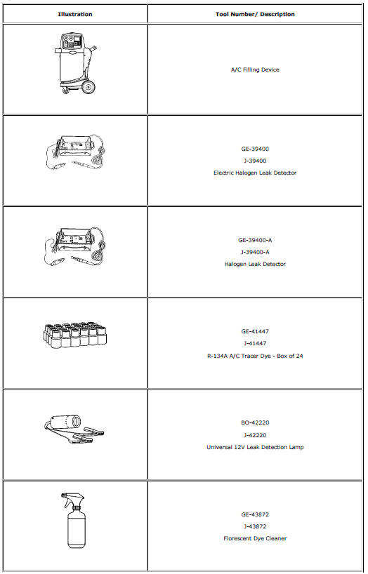
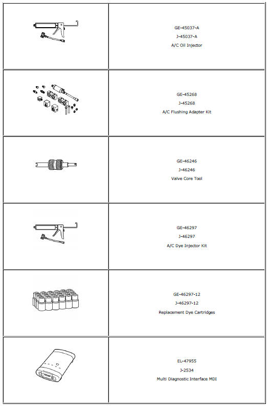
Special Tools and Equipment
 Floor Air Outlet Duct Replacement - Right Side (Right Hand Drive)
Removal Procedure
Remove instrument outer trim cover -- right side. Refer to Instrument
Panel Outer Trim Cover Replacement - Right Side.
Remove instrument panel lower trim pad cov ...
 Additional links
Instrument Cluster Replacement
Preliminary Procedure
Remove instrument panel lower cluster trim plate. Refer to Instrument
Panel Cluster Lower Trim Plate Replacement.
Remove instrument p ...
Other materials:
Automatic Transmission Fluid
How to Check Automatic Transmission Fluid
It is not necessary to check the transmission fluid level.
A transmission fluid leak is the only reason for fluid loss. If a leak occurs,
take the vehicle to your dealer and have it repaired as soon as possible.
The vehicle is not equipped with a transm ...
Windshield Wiper/Washer
The windshield wiper/washer lever is on the right side of the steering column.
With the ignition in ACC/ ACCESSORY or ON/RUN, move the windshield wiper lever to
select the wiper speed.
HI: Use for fast wipes.
LO: Use for slow wipes.
INT: Move the lever up to INT for intermittent wipes, th ...
Installation Procedure
Align the rocker inner panel.
Drill 8 mm (5/16 in) for plug welding along the edges of the quarter
outer panel as noted from the original panel.
Clean and prepare the attaching surfaces for welding.
Position the rocker inner panel on the vehicle.
Verify the fit of ...
