Chevrolet Cruze Repair Manual: Installation Procedure

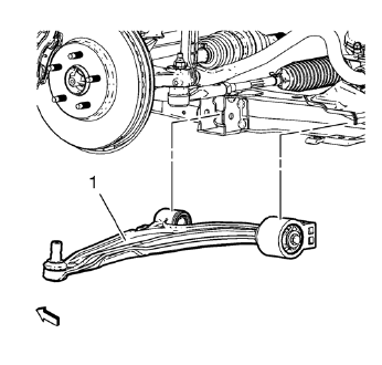
- Position the lower control arm (1) in the cradle.

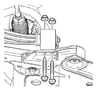
- Install and hand tighten the NEW rear lower control arm bushing nuts and bolts (1).

- Install and hand tighten the NEW front lower control arm nut and bolt (1).
Caution: Refer to Fastener Caution in the Preface section.

- Support the lower control arm with a hydraulic jack and lift the control arm into the neutral position.
- Tighten the front lower control arm bolt (1) to 70 N·m (52 lb ft) +75-90 degrees , using EN-45059 kit .
- Tighten the rear bushing to frame bolts to 55 N·m (41 lb ft) +45-60 degrees , using EN-45059 kit .
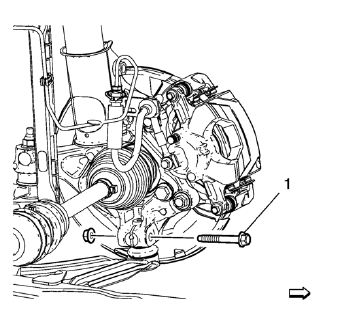
- Install the NEW ball joint to knuckle bolt and nut and tighten to 30 N·m
(22 lb ft) +60-75 degrees , using EN-45059 kit .
Lower the vehicle to the ground in order to tighten the control arm fasteners correctly.
- Remove the jack stand.
- Install the tire and wheel. Refer to Tire and Wheel Removal and Installation.
- Lower the vehicle.
 Removal Procedure
Raise and support the vehicle. Refer to Lifting and Jacking the
Vehicle.
Remove the tire and wheel. Refer to Tire and Wheel Removal and
Installation.
Note: DO NOT re-use the lower ...
 Front Lower Control Arm Bushing Replacement
Preliminary Procedure
Raise and support the vehicle. Refer to Lifting and Jacking the
Vehicle.
Remove the tire and wheel. Refer to Tire and Wheel Removal and
Installation.
Remo ...
Other materials:
Windshield Washer Nozzle Hose Replacement
Preliminary Procedure
Remove the hood insulator. Refer to
Hood Insulator Replacement.
Place a clean container under the front driver side near where the
windshield washer nozzle and windshield washer pump
hose will be disconnected.
Recover all lost windshield washer solven ...
Installation Procedure
Remove all mounds or loose pieces of urethane adhesive from the
pinch-weld area.
Inspect for any of the following problems in order to help prevent
future breakage of the window:
High weld
Solder spots
Hardened sealer
Any other obstruction or irregularity in the pinch-weld fla ...
Wipers and Washers
Specifications
Wiper/Washer Schematics
Windshield Wiper and Washer Switch Replacement
Preliminary Procedure
Remove the steering column trim covers. Refer to Steering Column Lower Trim
Cover Replacement.
Windshield Wiper and Washer Switch
Procedure
Disconnect any elect ...
