Chevrolet Cruze Repair Manual: Rear Axle Bushing Replacement
Special Tools
- CH 6616 Hydraulic Hand Pump
- CH 6615-10 Hydraulic Cylinder
- CH-48377-1 Chisel
- CH-49233 Adapter
- CH 906-42 Adapter
For equivalent regional tools. Refer to Special Tools
Removal Procedure
Warning: Use of eye goggles is necessary to prevent personal injury.
- Remove the rear axle. Refer to Rear Axle Replacement
- With the aid of second mechanic, place rear axle onto work bench.
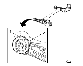
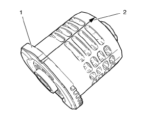
- Mark installation position (dashed line) for rear axle bushing (2) on rear axle using a permanent marker.
Use upper gap (1) of bushing for alignment.
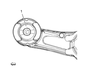
- Drill 8 times all around through rubber (1) bushings with drill 10 mm (0.4 in)
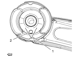
- Jigsaw carefully a V-cut (dashed line) into lower side (1) of rear axle bushing. Use lowest bore (2) to insert saw.
- Remove bushing (1), using CH-48377-1 chisel (2) and a hammer. Insert CH-48377-1 chisel on place of V-cut.
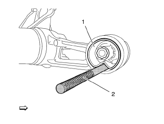
- Mark installation position (2) of NEW rear axle bushing (1) as shown in graphic above
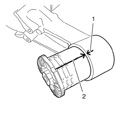
- Align bushing marking (2) to rear axle marking (1).
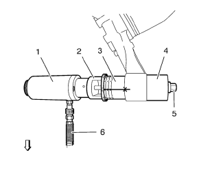
- Install the following components onto rear axle bushing and rear axle:
- CH 6615-10 cylinder (1).
- CH-49233 adapter (2).
- NEW rear axle bushing (3).
- CH 906-42 adapter (4)
- Install and tighten counter nut (5) onto spindle of CH 6615-10 cylinder (1)
- Connect pressure hose (6) of CH 6616 pump to CH 6615-10 cylinder
- Press carefully the rear axle bushing in to rear axle, using CH 6616 pump .
- When lift way of CH 6615-10 cylinder reaches stop, release pressure on CH 6616 pump , retighten counter nut (5) and press rear axle bushing in to rear axle until final installation position.
- Remove ALL special tools.
- Install rear axle. Refer to Rear Axle Replacement
 Rear Wheel Bearing and Hub Replacement (Drum Brake)
Special Tools
EN 45059 Torque Angle Sensor Kit
For equivalent regional tools, refer to Special Tools.
Removal Procedure
Raise and suitably support the vehicle. Refer to Lifting and ...
 Shock Absorber Replacement
Removal Procedure
Raise and suitably support the vehicle. Refer to Lifting and
Jacking the Vehicle.
Remove the tire and wheel assembly. Refer to Tire and Wheel Removal and
Installati ...
Other materials:
Service Publications Ordering Information
Service Manuals
Service Manuals have the diagnosis and repair information on the engines, transmission,
axle, suspension, brakes, electrical, steering, body, etc.
Service Bulletins
Service Bulletins give additional technical service information needed to knowledgeably
service General Motors c ...
OnStar® Destination Download
The destination download lets an OnStar® subscriber ask an OnStar Advisor to
download a destination to the navigation system. OnStar will send address information
and location coordinates of the destination into the navigation system.
Using Destination Download
If the navigation radio screen i ...
Fuel
Use of the recommended fuel is an important part of the proper maintenance of
this vehicle. To help keep the engine clean and maintain optimum vehicle performance,
we recommend the use of gasoline advertised as TOP TIER Detergent Gasoline.
Look for the TOP TIER label on the fuel pump to ensure ...
