Chevrolet Cruze Repair Manual: Rear Window Defogger Description and Operation
Rear Window Defogger System Components
The rear window defogger system consists of the following components:
- HVAC Control Module
- HVAC Control Head
- Rear Window Defogger Relay
- Rear Defogger Grid
- F28UA 40A Fuse
Rear Window Defogger Operation
The rear defog control system utilizes a single zone backlight design, driven with a single relay configuration. Additionally, up to two outside rear view mirrors can be heated if required. A switch for the customer to control the system is provided within the HVAC control head. Also included in the HVAC control head is an indicator to inform the customer with the current state of the system. The system is only operational when engine is running or during remote start.
Pressing the heated rear window switch on the HVAC control face plate causes the HVAC control head to send a serial data message to the HVAC control module requesting rear window defog operation. The HVAC control module upon receipt of the serial data message will provide voltage to the coil side of the rear window defogger relay, this will energize the relay causing the relay switch contacts to close allowing B+ voltage to flow through the rear defogger grid control circuit to the rear defogger grid.
When the rear heated window switch is pressed and the engine is running, the rear defog control system will remain active for 10 minutes.
After the initial cycle has lapsed, pressing the switch again will continue rear window defogger operation, but the cycle will only last 5 minutes. The rear defog control system will function continuously if the vehicle speed is greater than 70 kilometers per hour (45 mph).
Stationary Window Description
Most stationary windows, specifically windshields, are retained to the body with urethane adhesive which adheres the window to the body.
This increases structural integrity. The reinstallation of windows with urethane adhesive requires complete replacement of the urethane adhesive bead: The extended method (also known as long method, full strip or full cut) is the only recommended procedure for General Motors Vehicle.
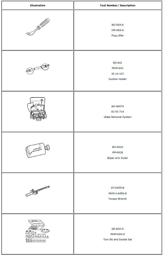
Special Tools and Equipment
 Power Windows Description and Operation
Power Windows System Components
The power window system consists of the following components:
Driver window switch
Passenger window switch
Left rear window switch
Right rear window switch
...
 Horns
Horns
Specifications
Horn Replacement
Preliminary Procedure
Remove the front bumper fascia. Refer to Front Bumper Fascia Replacement.
Horn Nut
Caution: Refer to Fastener Caution in the ...
Other materials:
Variable Effort Steering System Description and Operation
The Variable Effort Steering (VES) system or MAGNASTEER® varies the amount of
effort required to steer the vehicle as vehicle speed
changes. At low speeds, the system provides minimal steering effort for easy
turning and parking maneuvers. Steering effort is increased
at higher speeds to provi ...
Checking and Adding Power Steering Fluid
Caution: When adding fluid or making a complete fluid change, always
use the proper power steering fluid. Failure to use the proper fluid
will cause hose and seal damage and fluid leaks.
Clean the area surrounding the reservoir cap.
Remove the reservoir cap.
Inspect the power steeri ...
Instrument Panel Outer Air Outlet Replacement - Left Side
Preliminary Procedure
Remove instrument panel lower trim pad cover - left side. Refer to
Instrument Panel Lower Trim Pad Cover Replacement.
Remove instrument panel cluster trim plate. Refer to Instrument Panel
Cluster Trim Plate Replacement.
Remove instrument panel cluster lo ...
