
Chevrolet Cruze Repair Manual: Removal Procedure
Warning: Refer to Approved Equipment for Collision Repair Warning in the Preface section.
Warning: Refer to Glass and Sheet Metal Handling Warning in the Preface section.
- Disable the SIR System. Refer to SIR Disabling and Enabling.
- Disconnect the negative battery cable. Refer to Battery Negative Cable Disconnection and Connection.
- Remove all related panels and components.
- Visually inspect the damage. Repair as much of the damage as possible.
- Remove the sealers and anti-corrosion materials from the repair area, as necessary. Refer to Anti-Corrosion Treatment and Repair.
- Locate and mark all factory welds.
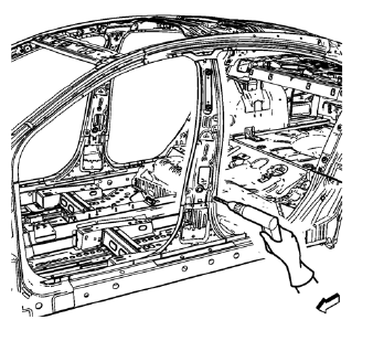
- Drill all factory welds lower. Note the number and location of welds for installation of the service assembly.
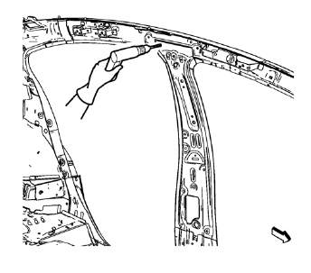
- Drill all factory welds upper. Note the number and location of welds for installation of the service assembly.
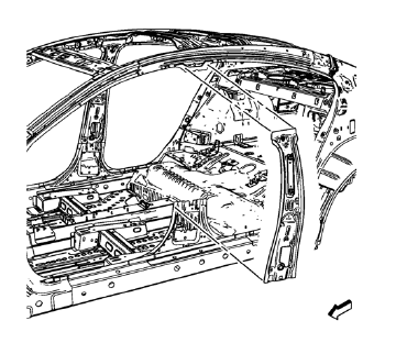
- Remove the damaged body lock pillar inner panel.
 Body Lock Pillar Inner Panel Replacement (MAG-Welding)
Note: According to different corrosion warranties, only the
regional mandatory joining methods are allowed. ...
 Installation Procedure
Drill 8 mm (5/16 in) for plug welding along the edges of the service
panel as noted from the original
panel.
Clean and prepare the attaching surfaces for welding.
...
Other materials:
Ultra High Strength Dual Phase Steel
This information provides repair recommendations and general guidelines for
steel classified as Ultra High Strength Dual Phase Steel (Dual
Phase Steel with a tensile strength greater than 800 MPa), also known as DPX.
General Motors recommends the following when repairing or replacing this type ...
Installation Procedure
Prepare all mating surfaces as necessary.
Align the body lock pillar outer panel reinforcement.
Create 8 x 24 mm (5/16 x 15/16 in) slots for MIG-brazing upper (1) and
lower (2).
Clean and prepare the attaching surfaces for spot welding and brazing.
Position the body loc ...
Rear Wheel Bearing and Hub Replacement (Disc Brake)
Special Tools
EN 45059 Torque Angle Sensor Kit
For equivalent regional tools, refer to Special Tools.
Removal Procedure
Raise and suitably support the vehicle. Refer to Lifting and
Jacking the Vehicle.
Remove the tire and wheel assembly. Refer to Tire and Wheel Removal and
...
