
Chevrolet Cruze Repair Manual: Removal Procedure
Warning: Refer to Approved Equipment for Collision Repair Warning in the Preface section.
Warning: Refer to Glass and Sheet Metal Handling Warning in the Preface section.
- Disable the SIR System. Refer to SIR Disabling and Enabling.
- Disconnect the negative battery cable. Refer to Battery Negative Cable Disconnection and Connection.
- Remove all related panels and components
- Visually inspect the damage. Repair as much of the damage as possible.
- Remove the sealers and anti-corrosion materials from the repair area, as necessary. Refer to Anti-Corrosion Treatment and Repair.
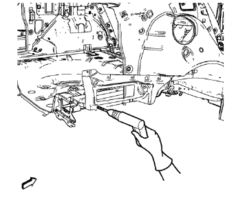
- Locate and mark all the necessary factory welds of the body side outer lower panel.
Note: Note the number and location of welds for installation of the service assembly.
- Drill all factory welds.
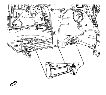
- Remove the body side outer lower panel.
 Body Side Outer Lower Panel Replacement (MAG-Welding)
Note: According to different corrosion warranties, only the
regional mandatory joining methods are allowed. ...
 Installation Procedure
Drill 8 mm (5/16 in) for plug welding along the edges of the body side
outer lower panel as noted from the original panel.
Note: If the location of the original plug weld holes can not be ...
Other materials:
Automatic Transmission Fluid
How to Check Automatic Transmission Fluid
It is not necessary to check the transmission fluid level.
A transmission fluid leak is the only reason for fluid loss. If a leak occurs,
take the vehicle to your dealer and have it repaired as soon as possible.
The vehicle is not equipped with a transm ...
Removal Procedure
Warning: Refer to Glass and Sheet Metal Handling Warning in the Preface
section.
Disable the SIR System. Refer to SIR Disabling
and Enabling.
Disconnect the negative battery cable. Refer to Battery Negative Cable
Disconnection and Connection.
Remove the front side door. Refer t ...
Front Fog Lamp Bulb Replacement
Preliminary Procedures
Raise and support the vehicle. Refer to Lifting and Jacking the Vehicle
Disconnect the forward lamp electrical harness connector from the fog
lamp bulb socket.
Remove the Front Bumper Fascia Opening Lower Cover. Refer to Front
Bumper Fascia Opening Lowe ...
