Chevrolet Cruze Repair Manual: Removal Procedure
Warning: Refer to Approved Equipment for Collision Repair Warning in the Preface section.
Warning: Refer to Glass and Sheet Metal Handling Warning in the Preface section.
- Disable the SIR System. Refer to SIR Disabling and Enabling.
- Disconnect the negative battery cable. Refer to Battery Negative Cable Disconnection and Connection.
- Remove all related panels and components.
- Visually inspect the damage. Repair as much of the damage as possible.
- Remove the sealers and anti-corrosion materials from the repair area, as necessary. Refer to Anti-Corrosion Treatment and Repair.
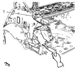
- Locate and mark all the necessary factory welds of the body rear end panel.
Note: Drill factory welds in area of the rear end upper panel reinforcement (1) from above. Drill holes are necessary for later plug welds.
- Drill all factory welds. Note the number and location of welds for installation of the service assembly.
- Remove the tail lamp pocket.
 Tail Lamp Pocket Replacement (MAG-Welding)
Note: According to different corrosion warranties, only the
regional mandatory joining methods are allowed. ...
 Installation Procedure
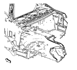
Drill 8 mm (5/16 in) for plug welding along the edges of the tail lamp
pocket as noted from the original panel.
Note:
Clean and prepare the attaching surfaces for welding.
...
Other materials:
Steering Wheel Controls
For vehicles with audio steering wheel controls, some audio controls can be adjusted
at the steering wheel.
(Push to Talk): For vehicles with
a Bluetooth, OnStar, or navigation system, press to interact with those systems.
(Mute/End Call): Press to silence
the vehicle speakers only.
Pre ...
Vehicle Identification Number (VIN)
This legal identifier is in the front corner of the instrument panel, on the
left side of the vehicle. It can be seen through the windshield from outside. The
VIN also appears on the Vehicle Certification and Service Parts labels and certificates
of title and registration.
Engine Identifi ...
Rear Side Door Replacement
Preliminary Procedure
Remove the rear side door trim panel. Refer to Rear Side Door Trim
Replacement.
Rear Side Door Check Link Bolt
Caution: Refer to Fastener Caution in the Preface section.
Procedure
Remove the water deflector
Disconnect the door electrical connector.
Suppo ...
