
Chevrolet Cruze Repair Manual: Removal Procedure
Warning: Refer to Approved Equipment for Collision Repair Warning in the Preface section.
Warning: Refer to Collision Sectioning Warning in the Preface section.
Warning: Refer to Glass and Sheet Metal Handling Warning in the Preface section.
- Disable the SIR System. Refer to SIR Disabling and Enabling.
- Disconnect the negative battery cable. Refer to Battery Negative Cable Disconnection and Connection.
- Remove all related panels and components.
- Visually inspect the damage. Repair as much of the damage as possible.
- Remove the sealers and anti-corrosion materials from the repair area, as necessary. Refer to Anti-Corrosion Treatment and Repair.
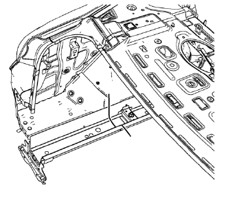
- Create cut lines on the rear side rail.
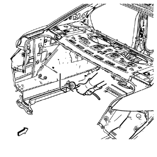
Note: Do not damage any other panels or reinforcements.
- Cut the panel where sectioning is to be performed.
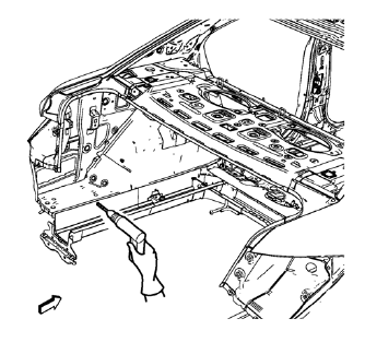
- Locate and mark all the necessary factory welds of the rear side rail.
- Drill all factory welds. Note the number and location of welds for installation of the service assembly.
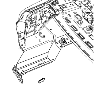
- Remove the damaged rear side rail.
 Rear Rail Sectioning (MAG-Welding)
Note: According to different corrosion warranties, only the
regional mandatory joining methods are allowed. ...
 Installation Procedure
Cut the rear side rail in corresponding locations to fit the remaining
original panel. The sectioning joint should be trimmed to allow a
gap of one-and-one-half-times the metal thickness a ...
Other materials:
Removal Procedure
Warning: Refer to Approved Equipment for Collision Repair Warning in the
Preface section.
Warning: Refer to Collision Sectioning Warning in the Preface section.
Warning: Refer to Glass and Sheet Metal Handling Warning in the Preface section.
Disable the SIR System. Refer to SIR Dis ...
Installation Procedure
Note: If the location of the original plug weld holes can not be
determined, space the plug weld holes every 40 mm (1½ in).
Drill 8 mm (5/16 in) for plug welding along the edges of the body rear
end panel as noted from the original panel.
Clean and prepare the attaching s ...
Tire Terminology and Definitions
Air Pressure: The amount of air inside the tire pressing outward on each
square inch of the tire. Air pressure is expressed in kPa (kilopascal) or psi (pounds
per square inch).
Accessory Weight: The combined weight of optional accessories. Some examples
of optional accessories are automatic t ...
