
Chevrolet Cruze Repair Manual: Front Fog Lamp Bezel Replacement
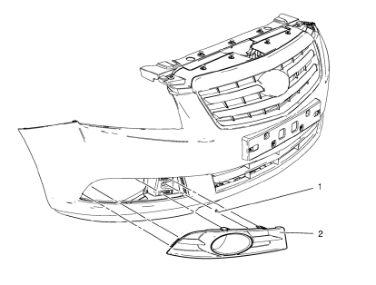
Preliminary Procedure
- Remove front bumper fascia. Refer to Front B 1. umper Fascia Replacement.
- Remove front fog lamp. Refer to Front Fog Lamp Replacement.
- Front Fog Lamp Bezel Screw
Caution: Refer to Fastener Caution in the Preface section.
Tighten 2.5 N·m (23 lb in)
- Front Fog Lamp Bezel
Procedure
- Disengage the four inner retainer tabs securing the bezel to the front bumper fascia.
- Pull outward from the outer edge in order to release the outer retention clips securing the bezel to the front bumper fascia.
- Remove the front fog lamp bezel.
Front Bumper Fascia Front Tow Eye Access Hole Cover Replacement
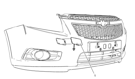
- Front Bumper Fascia Front Tow Eye Access Hole Cover
Front Side Door Window Frame Rear Cover Replacement
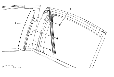
- Front Side Door Window Frame Cover Bolt (Qty: 3)
Caution: Refer to Fastener Caution in the Preface section.
Tip
Pull the window weatherstrip aside.
Tighten
2 N·m (18 lb in)
- Front Side Door Window Frame Cover
Rear Side Door Window Frame Front Cover Replacement
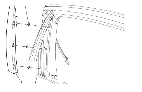
- Rear Side Door Window Frame Front Cover Bolt (Qty: 3)
Caution: Refer to Fastener Caution in the Preface section.
Tip
Pull the window weatherstrip aside.
Tighten 2 N·m (18 lb in)
- Rear Side Door Window Frame Front Cover
Radiator Grille Emblem/Nameplate Replacement (Chevrolet)
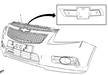
- Radiator Grille Emblem Screw (Qty: 2)
Caution: Refer to Fastener Caution in the Preface section.
Tighten 2.5 N·m(22 lb in)
- Radiator Grille Emblem Assembly
 Front Fender Emblem/Nameplate Replacement (1.8L 2H0 or 2.0L Diesel)
Front Fender Emblem Assembly
Caution: Refer to Exterior Trim Emblem Removal Caution in the
Preface section.
Procedure
The part and surface should be 21°C (70°F) prior to installation. The ...
 Rear Compartment Lid Emblem/Nameplate Replacement (Bowtie)
Rear Compartment Lid Emblem Assembly
Caution: Refer to Exterior Trim Emblem Removal Caution in the
Preface section.
Procedure
The part and surface should be 21°C (70°F) prior to installati ...
Other materials:
Windshield Washer Pump Seal Replacement
Removal Procedure
Open the hood.
Remove the windshield washer pump. Refer to Windshield Washer Pump
Replacement
Using a small flat-bladed tool, remove the washer pump terminal seal (1)
from the washer solvent container (2).
Installation Procedure
Position the washer pump ...
Exit Lighting
The headlamps, taillamps, parking lamps, back-up lamps, and license plate lamps
come on at night, or in areas with limited lighting, when the key is removed from
the ignition.
The dome lamps also come on when the key is removed from the ignition. The exterior
lights and dome lamps remain on a ...
Installation Procedure
Drill 8 mm (5/16 in) for plug welding along the edges of the body side
outer lower panel as noted from the original panel.
Note: If the location of the original plug weld holes can not be
determined, space the plug weld holes every 40 mm (1½ in).
Clean and prepare the attac ...
