Chevrolet Cruze Owners Manual: Ignition Positions (Key Access)

The ignition switch has four different positions.
Notice: Using a tool to force the key to turn in the ignition could cause damage to the switch or break the key. Use the correct key, make sure it is all the way in, and turn it only with your hand.
If the key cannot be turned by hand, see your dealer.
The key must be fully extended to start the vehicle.
To shift out of P (Park), turn the ignition to ON/RUN and apply the brake pedal.
1 (STOPPING THE ENGINE/LOCK/ OFF):
When the vehicle is stopped, turn the ignition switch to LOCK/ OFF to turn the engine off. Retained Accessory Power (RAP) will remain active. See Retained Accessory Power (RAP) on page 9‑22.
This is the only position from which the key can be removed. This locks the steering wheel, ignition, and automatic transmission.
The ignition switch can bind in the LOCK/OFF position with the wheels turned off center. If this happens, move the steering wheel from right to left while turning the key to ACC/ ACCESSORY. If this does not work, then the vehicle needs service.
Do not turn the engine off when the vehicle is moving. This will cause a loss of power assist in the brake and steering systems and disable the airbags.
If the vehicle must be shut off in an emergency: 1. Brake using a firm and steady pressure. Do not pump the brakes repeatedly. This may deplete power assist, requiring increased brake pedal force.
2. Shift the vehicle to Neutral. This can be done while the vehicle is moving. After shifting to Neutral, continue to firmly apply the brakes and steer the vehicle to a safe location.
3. Come to a complete stop. Shift to P (Park) with an automatic transmission, or Neutral with a manual transmission. Turn the ignition to LOCK/OFF.
4. Set the parking brake.
WARNING
Turning off the vehicle while moving may cause loss of power assist in the brake and steering systems and disable the airbags.
While driving, only shut the vehicle off in an emergency.
If the vehicle cannot be pulled over, and must be shut off while driving, turn the ignition to ACC/ ACCESSORY.
2 (ACC/ACCESSORY):
This position provides power to some of the electrical accessories. It unlocks the steering wheel and ignition. To move the key from ACC/ ACCESSORY to LOCK/OFF, push in the key and then turn it to LOCK/OFF.
3 (ON/RUN):
The ignition switch stays in this position when the engine is running. This position can be used to operate the electrical accessories, including the ventilation fan and 12-volt power outlet, as well as to display some warning and indicator lights. This position can also be used for service and diagnostics, and to verify the proper operation of the malfunction indicator lamp as may be required for emission inspection purposes. The transmission is also unlocked in this position on automatic transmission vehicles.
The battery could be drained if the key is left in the ACC/ACCESSORY or ON/RUN position with the engine off. The vehicle might not start if the battery is allowed to drain for an extended period of time.
4 (START): This position starts the engine. When the engine starts, release the key. The ignition switch will return to ON/RUN for normal driving.
A warning tone sounds when the driver door is opened if the ignition is still in ACC/ACCESSORY and the key is in the ignition.
Key Lock Release

Vehicles with an automatic transmission are equipped with an electronic key lock release system.
The key lock release is designed to prevent ignition key removal unless the shift lever is in P (Park).
The key lock release is always functional except in the case of an uncharged or low voltage (less than 9-volt) battery. If the vehicle has an uncharged battery or a battery with low voltage, try charging or jump starting the battery.
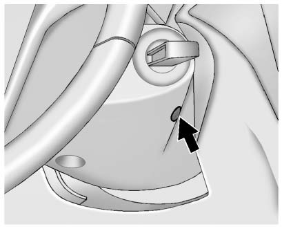
If charging or jump starting the battery does not work, locate the hole below the ignition lock. Insert a flat bladed tool or another key from the key chain into the opening.
When the lever can be felt, actuate the lever toward the driver, and remove the key from the ignition.
 New Vehicle Break-In
Notice: The vehicle does not need an elaborate break-in. But it will
perform better in the long run if you follow these guidelines:
Х Do not drive at any one constant speed, fast or slow, for the f ...
 Ignition Positions (Keyless Access)
The vehicle has an electronic keyless ignition with pushbutton start.
Pressing the button cycles it through three modes, ACC/ACCESSORY, ON/RUN/START,
and Stopping the Engine/OFF.
The transmitter ...
Other materials:
Tire Chains
WARNING
Do not use tire chains. There is not enough clearance. Tire chains used on
a vehicle without the proper amount of clearance can cause damage to the brakes,
suspension, or other vehicle parts. The area damaged by the tire chains could cause
loss of control and a crash. Use another type ...
Frontal SIR System Description
The frontal supplemental inflatable restraint (SIR) system consists of the
following components:
AIR BAG indicator located in the instrument cluster
Inflatable restraint sensing and diagnostic module (SDM)
Inflatable restraint passenger presence detection system
Inflatable restraint Pass ...
Installation Procedure
Create 8 24 mm (5/16 x 15/16 in) slots for MIG-brazing along the edges
of the underbody rear side rail reinforcement as noted from
the original panel.
Clean and prepare the attaching surfaces for
brazing.
Position the underbody rear side rail reinforcement on the ve ...
