
Chevrolet Cruze Repair Manual: Shock Absorber Replacement
Removal Procedure
- Raise and suitably support the vehicle. Refer to Lifting and Jacking the Vehicle.
- Remove the tire and wheel assembly. Refer to Tire and Wheel Removal and Installation.
- Support the rear axle with a tall jack stand near the shock absorber.
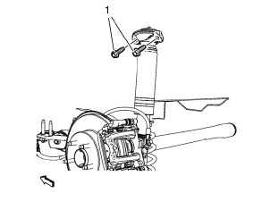
- Remove the upper shock absorber bolts (1).
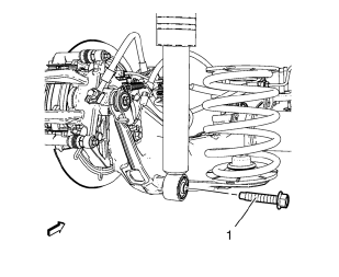
- Remove the lower shock absorber bolt (1).
Installation Procedure
- Position the shock absorber to the vehicle.
Caution: Refer to Fastener Caution in the Preface section.
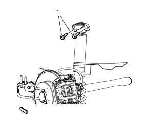
- Install NEW upper shock absorber bolts (1) and tighten to 100 N·m (74 lb in).
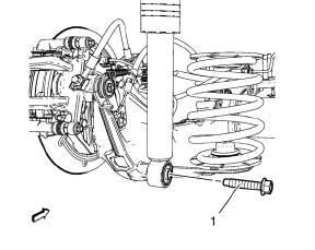
- Install NEW lower shock absorber bolt (1) and tighten to 150 N·m (111 lb ft) + 60°.
- Remove the jack stand.
- Install the rear tire and wheel assembly. Refer to Tire and Wheel Removal and Installation.
- Lower the vehicle.
 Rear Axle Bushing Replacement
Special Tools
CH 6616 Hydraulic Hand Pump
CH 6615-10 Hydraulic Cylinder
CH-48377-1 Chisel
CH-49233 Adapter
CH 906-42 Adapter
For equivalent regional tools. Refer to Special Tools
Remov ...
 Shock Absorber Disposal
Warning: Gas charged shock absorbers contain high pressure gas. Do
not remove the snap ring from inside the top of the tube. If the snap
ring is removed, the contents of the shock absorber will com ...
Other materials:
Symbols
The vehicle has components and labels that use symbols instead of text. Symbols
are shown along with the text describing the operation or information relating to
a specific component, control, message, gauge, or indicator.
: This symbol is shown when you need
to see your owner manual for addi ...
Removal Procedure
Warning: Refer to Approved Equipment for Collision Repair Warning in the
Preface section.
Warning: Refer to Collision Sectioning Warning in the Preface section.
Warning: Refer to Glass and Sheet Metal Handling Warning in the Preface section.
Disable the SIR System. Refer to SIR Dis ...
Using the Navigation System
Use the NAV button on the faceplate or Home Page to access the navigation map.
Press the NAV button again to change between alternative views of the normal
split and full map views.
The Menu screen button at the bottom right side of the display accesses the Navigation
Menu.
The touch-sens ...
