Chevrolet Cruze Repair Manual: Installation Procedure
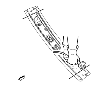
- Cut the roof front header panel in corresponding locations to fit the remaining original panel. The sectioning joint should be trimmed to allow a gap of one-and-one-half-times the metal thickness at the sectioning joint.
- Create a 50 mm (2 in) backing plate from the unused portion of the service part.
- Drill 8 mm (5/16 in) along the sectioning cut on the remaining original part. Locate these holes 13 mm (1/2 in) from the edge of part and spaced 40 mm (1 1/2 in) apart.
- Prepare all mating surfaces as necessary.
- Fit the backing plates halfway into the sectioning joints, clamp in place and plug weld to the vehicle.
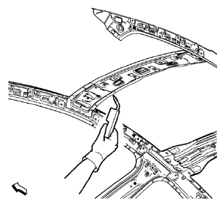
- Align roof front header panel.
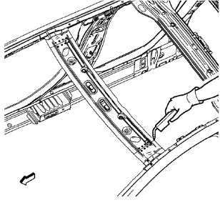
- Plug weld accordingly.
- To create a solid weld with minimum heat distortion, make 25 mm (1 in) stitch welds along the seam with 25 mm (1 in) gaps between them. Then go back and complete the stitch weld.
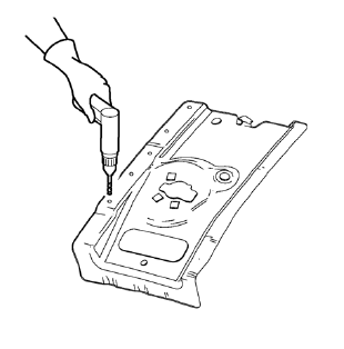
- Drill 8 mm (5/16 in) for plug welding along the edges of the roof panel front bracket right as noted from the original panel.
- Clean and prepare the attaching surfaces for welding.
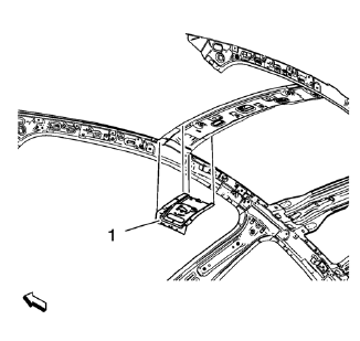
- Position the roof panel front bracket right (1) on the vehicle.
- Verify the fit of the roof panel front bracket.
- Clamp the roof panel front bracket right into position.
- Plug weld accordingly.
- Proceed the same way with the roof panel front bracket left.
- Apply the sealers and anti-corrosion materials to the repair area, as necessary. Refer to Anti-Corrosion Treatment and Repair.
- Paint the repaired area. Refer to Basecoat/Clearcoat Paint Systems.
- Install all related panels and components.
- Connect the negative battery cable. Refer to Battery Negative Cable Disconnection and Connection.
- Enable the SIR system. Refer to SIR Disabling and Enabling.
 Removal Procedure
Warning: Refer to Approved Equipment for Collision Repair Warning in the
Preface section.
Warning: Refer to Collision Sectioning Warning in the Preface section.
Warning: Refer to Glass and She ...
 Roof Front Header Panel Replacement (MIG-Brazing)
Note: According to different corrosion warranties, only the
regional mandatory joining methods are allowed. ...
Other materials:
Driver or Passenger Seat Replacement
Removal Procedure
Warning: Refer to SIR Warning in the Preface section.
Warning: When carrying a live inflator module, make sure the bag
opening is pointed away from you. This minimizes the chance of
injury in the case of an accidental deployment. Never carry the inflator module
by the wi ...
Adding Equipment to the Airbag-Equipped Vehicle
Adding accessories that change the vehicle's frame, bumper system, height, front
end, or side sheet metal, may keep the airbag system from working properly. The
operation of the airbag system can also be affected by changing or moving any parts
of the front seats, safety belts, the airbag ...
Front Seat Belt System
The front seat belt system includes a driver and passenger seat belt
pretensioner retractor. Both front seat belt pretensioners includes a
seat belt switch in the seat buckle which controls a reminder lamp and a tone
alarm.
Note: The front passenger seat is equipped with a passenger
presence ...
