Chevrolet Cruze Repair Manual: Installation Procedure
- Cut the roof front header panel in corresponding locations to fit the remaining original panel. The sectioning joint should be trimmed to allow a gap of one-and-one-half-times the metal thickness at the sectioning joint.
- Create a 50 mm (2 in) backing plate from the unused portion of the service part.
- Drill 8 mm (5/16 in) along the sectioning cut on the remaining original part. Locate these holes 13 mm (1/2 in) from the edge of part and spaced 40 mm (1 1/2 in) apart.
- Prepare all mating surfaces as necessary.
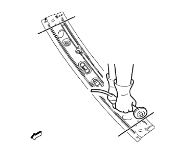
- Fit the backing plates halfway into the sectioning joints, clamp in place and braze to the vehicle
- Align roof front header panel.

- Braze accordingly.
- To create a solid braze with minimum heat distortion, make 25 mm (1 in) stitch brazes along the seam with 25 mm (1 in) gaps between them. Then go back and complete the stitch braze.
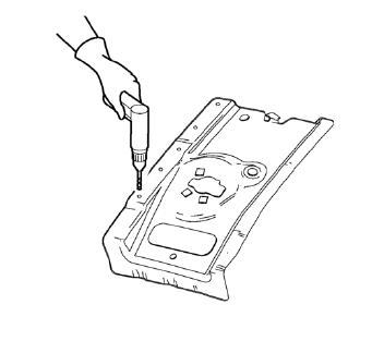
- Create 6 x 20 mm (4/16 x 12/16 in) slots for MIG-brazing along the edges of the roof panel front bracket right.
- Clean and prepare the attaching surfaces for brazing.
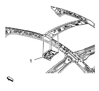
- Position the roof panel front bracket right (1) on the vehicle.
- Verify the fit of the roof panel front bracket.
- Clamp the roof panel front bracket right into position.
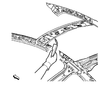
- Braze accordingly.
- Proceed the same way with the roof panel front bracket left.
- Apply the sealers and anti-corrosion materials to the repair area, as necessary. Refer to Anti-Corrosion Treatment and Repair.
- Paint the repaired area. Refer to Basecoat/Clearcoat Paint Systems.
- Install all related panels and components.
- Connect the negative battery cable. Refer to Battery Negative Cable Disconnection and Connection.
- Enable the SIR system. Refer to SIR Disabling and Enabling.
 Removal Procedure
Warning: Refer to Approved Equipment for Collision Repair Warning in the
Preface section.
Warning: Refer to Collision Sectioning Warning in the Preface section.
Warning: Refer to Glass and She ...
 Roof Rear Header Panel Replacement (MAG-Welding)
Note: According to different corrosion warranties, only the
regional mandatory joining methods are allowed. ...
Other materials:
Windshield Wiper/Washer
The windshield wiper/washer lever is on the right side of the steering column.
With the ignition in ACC/ ACCESSORY or ON/RUN, move the windshield wiper lever to
select the wiper speed.
HI: Use for fast wipes.
LO: Use for slow wipes.
INT: Move the lever up to INT for intermittent wipes, th ...
Floor Mats
WARNING
If a floor mat is the wrong size or is not properly installed, it can interfere
with the pedals.
Interference with the pedals can cause unintended acceleration and/or increased
stopping distance which can cause a crash and injury. Make sure the floor mat does
not interfere with the p ...
Front Side Door Wiring Harness Replacement
Preliminary Procedure
Remove the front side door inner panel trim. Refer to Front Side Door Trim
Replacement.
Front Side Door Wiring Harness
Warning: Unless directed otherwise, the ignition and start switch must be
in the OFF or LOCK position, and all electrical
loads must be OFF before ...
