Chevrolet Cruze Repair Manual: Installation Procedure
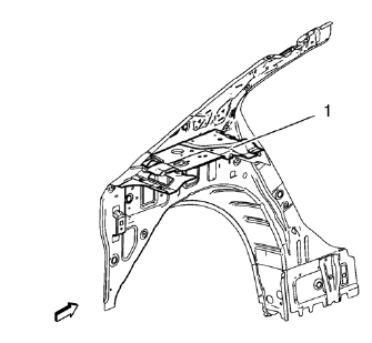
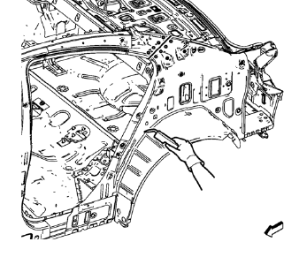
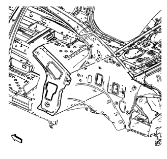
- Remove rear end upper panel extension (1) from service part.
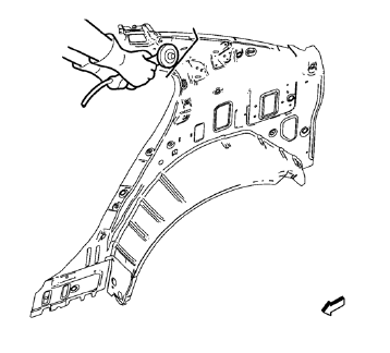
- Cut the body side inner panel in corresponding locations to fit the remaining original panel. The sectioning joint should be trimmed to allow a gap of one-and-one-half-times the metal thickness at the sectioning joint.
- Create a 50 mm (2 in) backing plate from the unused portion of the service part.
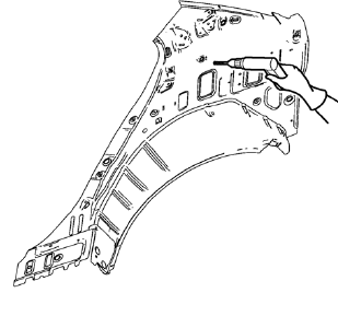
- Create 5 x 18 mm (4/16 x 11/16 in) slots for MIG-brazing along the sectioning cut on the remaining original part. Locate these holes 13 mm (1/2 in) from the edge of part and spaced 40 mm (1 1/2 in) apart.
- Prepare all mating surfaces as necessary.
- Fit the backing plates halfway into the sectioning joints, clamp in place and plug weld to the vehicle.
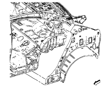
- Align the body side inner panel.
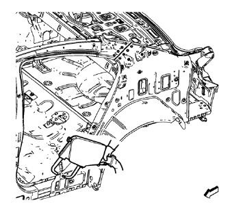
- Create 6 x 20 mm (4/16 x 12/16 in) slots for MIG-brazing in locations where you can not apply a resistance spot welder.
- Clean and prepare the attaching surfaces for spot welding and brazing.
Note: In MIG-brazing areas 50 mm (2 in) must be kept clear of structural adhesive.
- Apply structural adhesive to all attaching surfaces
- Position the body side inner panel.
- Verify the fit of the panel.
- Clamp the body side inner panel into position.
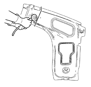
- Braze accordingly.
- Spot weld accordingly
- To create a solid braze with minimum heat distortion, make 25 mm (1 in) stitch brazes along the seam with 25 mm (1 in) gaps between them. Then go back and complete the stitch braze.
- Cut the body lock pillar upper reinforcement in corresponding locations to fit the remaining original panel. The sectioning joint should be trimmed to allow a gap of one-and-one-half-times the metal thickness at the sectioning joint.
- Create a 50 mm (2 in) backing plate from the unused portion of the service part.
- Create 5 x 18 mm (4/16 x 11/16 in) slots for MIG-brazing along the sectioning cut on the remaining original part. Locate these holes 13 mm (1/2 in) from the edge of part and spaced 40 mm (1 1/2 in) apart.
- Prepare all mating surfaces as necessary.
- Fit the backing plates halfway into the sectioning joints, clamp in place and braze to the vehicle.
- Align the body lock pillar upper reinforcement.
- Create 6 x 20 mm (4/16 x 12/16 in) slots for MIG-brazing in locations where you can not apply a resistance spot welder.
- Clean and prepare the attaching surfaces for spot welding and brazing.
Note: In MIG-brazing areas 50 mm (2 in) must be kept clear of structural adhesive.
- Apply structural adhesive to all attaching surfaces
- Position the body lock pillar upper reinforcement.
- Verify the fit of the panel.
- Clamp the body lock pillar upper reinforcement into position.
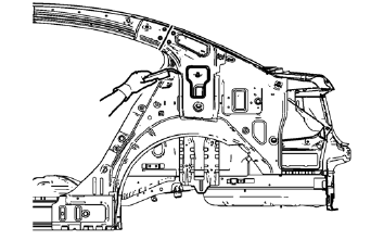
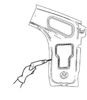
- Braze accordingly.
- Spot weld accordingly.
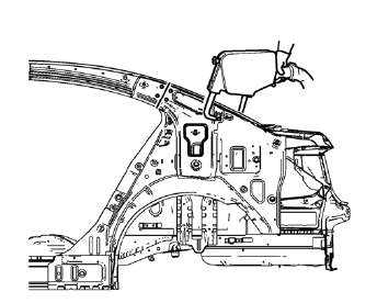
- Apply the sealers and anti-corrosion materials to the repair area, as necessary. Refer to Anti-Corrosion Treatment and Repair.
- Paint the repaired area. Refer to Basecoat/Clearcoat Paint Systems.
- Install all related panels and components.
- Connect the negative battery cable. Refer to Battery Negative Cable Disconnection and Connection.
- Enable the SIR system. Refer to SIR Disabling and Enabling.
 Removal Procedure
Warning: Refer to Approved Equipment for Collision Repair Warning in the
Preface section.
Warning: Refer to Collision Sectioning Warning in the Preface section.
Warning: Refer to Glass and She ...
 Body Side Outer Lower Panel Replacement (MAG-Welding)
Note: According to different corrosion warranties, only the
regional mandatory joining methods are allowed. ...
Other materials:
Jump Starting
If the battery has run down, try to use another vehicle and some jumper cables to start your vehicle.
Be sure to use the following steps to do it safely.
WARNING
Batteries can hurt you. They can be dangerous because:
• They contain acid that can burn you.
• They contain gas ...
Maps
This section includes basic information about the map database.
The data is stored in the internal flash memory that is used in the navigation
system.
Detailed Areas
Road network attributes are contained in the map database for detailed areas.
Attributes include information such as street nam ...
Front Fog Lamp Bulb Replacement
Preliminary Procedures
Raise and support the vehicle. Refer to Lifting and Jacking the Vehicle
Disconnect the forward lamp electrical harness connector from the fog
lamp bulb socket.
Remove the Front Bumper Fascia Opening Lower Cover. Refer to Front
Bumper Fascia Opening Lowe ...
