
Chevrolet Cruze Repair Manual: Installation Procedure
- Align the rear compartment floor panel.

- Drill 4 mm (3/16 in) for rivets along the edges of the rear compartment floor were you cant apply a resistance spot welder.
- Clean and prepare the attaching surfaces for spot welding and riveting.
- Apply structural adhesive to all attaching surfaces.
- Position the rear compartment floor panel on the vehicle.
- Verify the fit of the rear compartment floor panel.
- Clamp the rear compartment floor panel into position.
- Rivet the rear compartment floor panel.
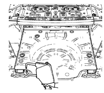
- Spot weld accordingly.
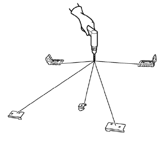
- Create 5 x 18 mm (4/16 x 11/16 in) slots for MIG-brazing along the edges of the floor panel rear reinforcement, the spare wheel carrier bracket and the rear wheelhouse panel rear brace as noted from the original panel.
- Clean and prepare the attaching surfaces for brazing.
- Position the floor panel rear reinforcement, the spare wheel carrier bracket and the rear wheelhouse panel rear brace on the vehicle.
- Verify the fit of the floor panel rear reinforcement, the spare wheel carrier bracket and the rear wheelhouse panel rear brace.
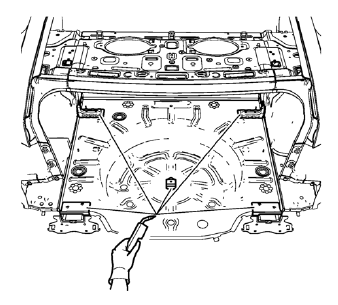
- Braze accordingly.
- Weld accordingly the weld studs as noted.
- Apply the sealers and anti-corrosion materials to the repair area, as necessary. Refer to Anti-Corrosion Treatment and Repair.
- Paint the repaired area. Refer to Basecoat/Clearcoat Paint Systems.
- Install all related panels and components
- Connect the negative battery cable. Refer to Battery Negative Cable Disconnection and Connection.
- Enable the SIR system. Refer to SIR Disabling and Enabling.
 Removal Procedure
Warning: Refer to Approved Equipment for Collision Repair Warning in the
Preface section.
Warning: Refer to Glass and Sheet Metal Handling Warning in the Preface section.
Disable the SIR Syst ...
 Rear Wheelhouse Panel Replacement (MAG-Welding)
Note: According to different corrosion warranties, only the
regional mandatory joining methods are allowed. ...
Other materials:
Installation Procedure
Align the rear side door outer panel.
Verify the fit of the rear side door outer panel.
Clamp the rear side door outer panel
into position.
Pre-flanging the flange with BO-6396 pliers and BO-6392 tool kit .
Continue to hammer in stages along the hem flanges.
App ...
Interior Windnoise
Warning: Refer to Assistant Driving Warning in the Preface section.
Interior windnoise is not heard when the window is lowered. Interior
windnoise is caused by the air leaving the inside of the vehicle
through a seal or a seam.
Tape over the relief valves to cause added air pressure wi ...
Checking and Adding Power Steering Fluid
Caution: When adding fluid or making a complete fluid change, always
use the proper power steering fluid. Failure to use the proper fluid
will cause hose and seal damage and fluid leaks.
Clean the area surrounding the reservoir cap.
Remove the reservoir cap.
Inspect the power steeri ...
