Chevrolet Cruze Repair Manual: Intermediate Steering Shaft Replacement
Removal Procedure
- Turn the steering wheel to the straight forward position and support it from movement
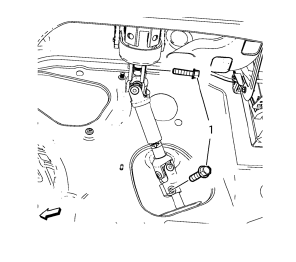
- Remove the 2 intermediate steering shaft bolts (1).
- Remove the intermediate steering shaft (1).
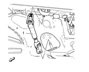
Installation Procedure
- Install the intermediate steering shaft (1).
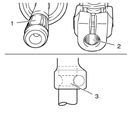
Note: The recess (2) of the fine toothing in the universal joint have to align precisely with the recess (1) of the fine toothing on the steering pinion. The bore in the universal joint has to align with the groove on the steering pinion (3).
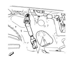
- Push universal joint onto steering pinion carefully as desribed above inthe note.
Caution: Refer to Fastener Caution in the Preface section.
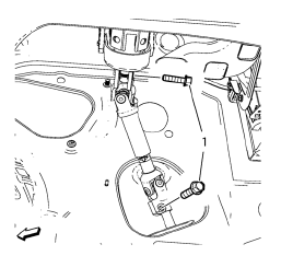
- Install the 2 intermediate steering shaft bolts (1). Tighten the intermediate steering shaft bolts 34 N·m (25 lb ft).
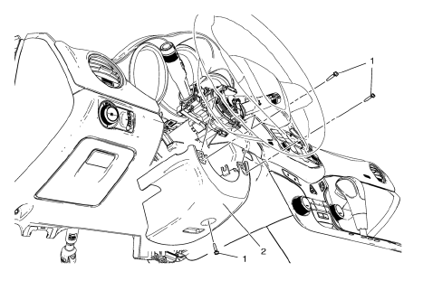
Steering Column Upper Trim Cover Replacement
Steering Column Upper Trim Cover
Procedure
Unclip the steering column upper trim cover from the steering column lower trim cover.
Steering Column Lower Trim Cover Replacement
Preliminary Procedure
Remove the steering column upper trim cover. Refer to Steering Column Upper Trim Cover Replacement.
- Steering Column Lower Trim Cover Bolt (Qty: 3)
Caution: Refer to Fastener Caution in the Preface section.
Tighten 2.5 N·m (22 lb in)
- Steering Column Lower Trim Cover
Procedure
Turn the steering wheel until the bolts are reachable.
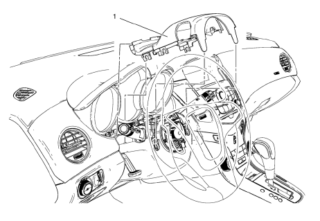
 Steering Wheel and Column
Specifications
...
 Turn Signal Switch Replacement
Preliminary Procedure
Remove the steering column upper trim cover. Refer to Steering Column
Upper Trim Cover Replacement.
Remove the steering column lower trim cover. Refer to Steer ...
Other materials:
Checking and Adding Power Steering Fluid
Caution: When adding fluid or making a complete fluid change, always
use the proper power steering fluid. Failure to use the proper fluid
will cause hose and seal damage and fluid leaks.
Clean the area surrounding the reservoir cap.
Remove the reservoir cap.
Inspect the power steeri ...
Roof
Sunroof
The sunroof only operates when the ignition is in ON/RUN or ACC/ ACCESSORY, or
when Retained Accessory Power (RAP) is active.
To open or close the sunroof, press the open or close sunroof switch (1) to the
first detent position.
To express open or close the sunroof with the safety f ...
Installation Procedure
Note: If the location of the original plug weld holes can not be
determined, space the braze holes every 40 mm (1½ in).
Create 5 x 18 mm (4/16 x 11/16 in) slots for MIG-brazing along the edges
of the rear floor panel filler as noted from the original
panel.
Clean and prepare ...
