Chevrolet Cruze Repair Manual: Installation Procedure
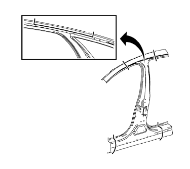
- Cut the body lock pillar outer panel in corresponding locations to fit the remaining original panel. The sectioning joint should be trimmed to allow a gap of one-and-one-half-times the metal thickness at the sectioning joint
- Create a 50 mm (2 in) backing plate from the unused portion of the service part.
- Drill 8 mm (5/16 in) along the sectioning cut on the remaining original part. Locate these holes 13 mm (1/2 in) from the edge of part and spaced 40 mm (1 1/2 in) apart.
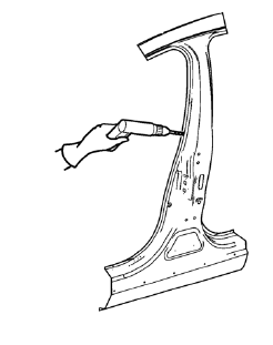
- Prepare all mating surfaces as necessary.
- Fit the backing plates halfway into the sectioning joints, clamp in place and plug weld to the vehicle.
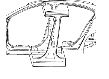
- Align the body lock pillar outer panel.
- Drill 8 mm (5/16 in) for plug welding along the edges of the body lock pillar outer panel as noted from the original panel.
- Clean and prepare the attaching surfaces for welding.
- Position the body lock pillar outer panel on the vehicle.
- Verify the fit of the body lock pillar outer panel.
- Clamp the body lock pillar outer panel into position.
- Plug weld accordingly.
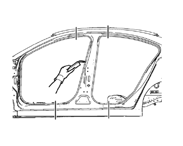
- To create a solid weld with minimum heat distortion, make 25 mm (1 in) stitch welds along the seam with 25 mm (1 in) gaps between them. Then go back and complete the stitch weld.
- Apply the sealers and anti-corrosion materials to the repair area, as necessary. Refer to Anti-Corrosion Treatment and Repair.
- Paint the repaired area. Refer to Basecoat/Clearcoat Paint Systems.
- Install all related panels and components.
- Connect the negative battery cable. Refer to Battery Negative Cable Disconnection and Connection.
- Enable the SIR system. Refer to SIR Disabling and Enabling.
 Removal Procedure
Warning: Refer to Approved Equipment for Collision Repair Warning in the
Preface section.
Warning: Refer to Collision Sectioning Warning in the Preface section.
Warning: Refer to Glass and She ...
 Body Lock Pillar Outer Panel Sectioning (MIG-Brazing)
Note: According to different corrosion warranties, only the
regional mandatory joining methods are allowed. ...
Other materials:
Front Side Door Replacement
Preliminary Procedure
Remove the front side door trim panel. Refer to Front Side Door Trim
Replacement.
Front Side Door Check Link Bolt
Caution: Refer to Fastener Caution in the Preface section.
Procedure
Remove the water deflector.
Disconnect the door electrical connector.
Su ...
StabiliTrak® System
The vehicle has a vehicle stability enhancement system called StabiliTrak. It
is an advanced computer controlled system that assists with directional control
of the vehicle in difficult driving conditions.
StabiliTrak activates when the computer senses a difference between the intended
path, ...
If the Vehicle Is Stuck
Slowly and cautiously spin the wheels to free the vehicle when stuck in sand,
mud, ice, or snow.
If stuck too severely for the traction system to free the vehicle, turn the traction
system off and use the rocking method.
WARNING
If the vehicle's tires spin at high speed, they can explode, ...
