Chevrolet Cruze Owners Manual: Maintenance Replacement Parts
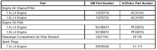
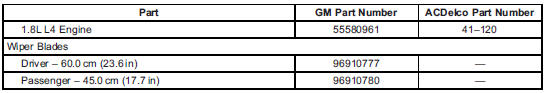
Replacement parts identified here by name, part number, or specification can be obtained from your dealer.

 Maintenance Records
After the scheduled services are performed, record the date, odometer reading,
who performed the service, and the type of services performed in the boxes provided.
Retain all maintenance receipts. ...
Other materials:
Customer Assistance Offices
Chevrolet encourages customers to call the toll-free number for assistance. However,
if a customer wishes to write or e-mail Chevrolet, the letter should be addressed
to:
United States and Puerto Rico
Chevrolet Motor Division
Chevrolet Customer Assistance Center
P.O. Box 33170
Detroit, MI 4 ...
Installation Procedure
Clean and prepare the attaching surfaces for brazing.
Apply structural adhesive to the attaching surfaces.
Position the rear bumper impact bar stud plate on the vehicle.
Verify the fit of the rear bumper impact bar stud plate
Clamp the rear bumper impact bar stud plate into ...
Shifting out of Park
This vehicle is equipped with an automatic transmission shift lock control system.
The shift lock is designed to:
• Prevent ignition key removal unless the shift lever is in P (Park) with the shift
lever button fully released.
• Prevent movement of the shift lever out of P (Park) unless the ig ...
