Chevrolet Cruze Repair Manual: Rear Brake Rotor Replacement
Special Tools
- CH 41013 Rotor Resurfacing Kit
- CH 42450-A Wheel Hub Resurfacing Kit
For equivalent regional tools, refer to Special Tools.
Removal Procedure
Warning: Refer to Brake Dust Warning in the Preface section.

- Remove rear brake caliper bracket. Refer to Rear Brake Caliper Bracket Replacement
- Matchmark the position of the brake rotor to the wheel studs.
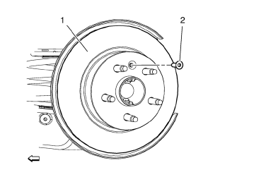
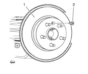
- Remove the rear brake rotor bolt (2).
- Remove rear brake rotor (1) from the wheel hub.
Installation Procedure
- Using the CH 42450-A kit , thoroughly clean any rust or corrosion from the mating surface of the hub/axle flange.
- Using the CH 41013 kit , thoroughly clean any rust or corrosion from the mating surface and mounting surface of the brake rotor.
- Inspect the mating surfaces of the hub/axle flange and the rotor to ensure that there are no foreign particles or debris remaining.

- Install the brake rotor (1) to the hub/axle flange. Use the matchmark made prior to removal for proper orientation to the flange.
Caution: Refer to Fastener Caution in the Preface section.
- Install rear brake rotor bolt (2) and tighten to 7 N·m (62 lb in).
- If the brake rotor was removed and installed as part of a brake system repair, measure the assembled LRO of the brake rotor to ensure optimum performance of the disc brakes. Refer to Brake Rotor Assembled Lateral Runout Measurement.
- If the brake rotor assembled LRO measurement exceeds the specification, bring the LRO to within specifications. Refer to Brake Rotor Assembled Lateral Runout Correction.
 Front Wheel Drive Shaft Replacement - Right Side
Special Tools
CH-313 Slide Hammer
CH-6003 Axle Shaft Remover
CH-49376 Holding Wrench
CH-49400 Hub Spindle Remover
DT-6332 Seal Protector
EN-956-1 Extension
For equivalent regional too ...
 Brake Drum Replacement
Special Tools
CH 41013 Rotor Resurfacing Kit
CH 42450-A Wheel Hub Resurfacing Kit
For equivalent regional tools, refer to Special Tools.
Removal Procedure
Warning: Refer to Brake Dust Warni ...
Other materials:
Steering Wheel Inflatable Restraint Module Replacement
Removal Procedure
Warning: When carrying a live inflator module, make sure the bag opening
is pointed away from you. This minimizes the chance of injury
in the case of an accidental deployment. Never carry the inflator module by the
wires. Never carry the inflator module by the connector on
t ...
Rear Compartment Lid Emblem/Nameplate Replacement (CDX)
Rear Compartment Lid Emblem Assembly
Caution: Refer to Exterior Trim Emblem Removal Caution in the Preface
section.
Procedure
The part and surface should be 21°C (70°F) prior to installation. The
vehicle should remain 21°C (70°F) for
one hour after assembly to allow adhesive to deve ...
Odometer
The odometer shows how far the vehicle has been driven, in either kilometers
or miles.
This vehicle has a tamper-resistant odometer. The digital odometer will read
999,999 if it is turned back.
If the vehicle needs a new odometer installed, it must be set to the mileage
total of the old odom ...
