
Chevrolet Cruze Repair Manual: Rear Suspension Description and Operation
This vehicle has a semi-independent twist-beam rear suspension system consisting of the following components:
- An axle with integral trailing arms
- AV shaped twisting cross beam
- Two coil springs
- Two shock absorbers
Axle Assembly
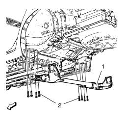
The axle assembly (1) attaches to the underbody through a rubber bushing and bracket located at the front of each integral trailing arm.
The brackets are attached to the underbody side rails with bolts (2). The axle structure itself maintains the geometrical relationship of the wheels relative to the centerline of the body.
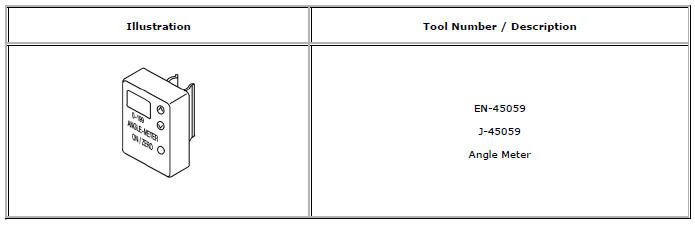
Special Tools and Equipment
 Wheel Stud Replacement
Removal Procedure
Raise and suitably support the vehicle. Refer to Lifting and
Jacking the Vehicle.
Remove the tire and wheel assembly. Refer to Tire and Wheel Removal and
Installati ...
 Tires and Wheels
Specifications
...
Other materials:
Stitcher Internet Radio
Stitcher SmartRadio™ is an Internet radio service that streams news, sports,
and entertainment shows through the audio system. Create personalized, on-demand
stations or discover new shows through Stitcher's preset stations. To set up an
account, download the application from the Android M ...
Installation Procedure
Cut the rear side rail in corresponding locations to fit the remaining
original panel. The sectioning joint should be trimmed to allow a
gap of one-and-one-half-times the metal thickness at the sectioning joint.
Create a 50 mm (2 in) backing plate from the unused portion of the
serv ...
Washer Fluid
What to Use
When windshield washer fluid is needed, be sure to read the manufacturer's instructions
before use. If operating the vehicle in an area where the temperature may fall below
freezing, use a fluid that has sufficient protection against freezing.
Adding Washer Fluid
Open the ca ...
