
Chevrolet Cruze Repair Manual: Removal Procedure
Warning: Refer to Approved Equipment for Collision Repair Warning in the Preface section.
Warning: Refer to Collision Sectioning Warning in the Preface section.
Warning: Refer to Glass and Sheet Metal Handling Warning in the Preface section.
- Disable the SIR System. Refer to SIR Disabling and Enabling.
- Disconnect the negative battery cable. Refer to Battery Negative Cable Disconnection and Connection.
- Remove all related panels and components.
- Visually inspect the damage. Repair as much of the damage as possible.
- Remove the sealers and anti-corrosion materials from the repair area, as necessary. Refer to Anti-Corrosion Treatment and Repair.
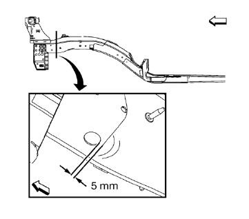
- Create cut lines on the front compartment front rail.
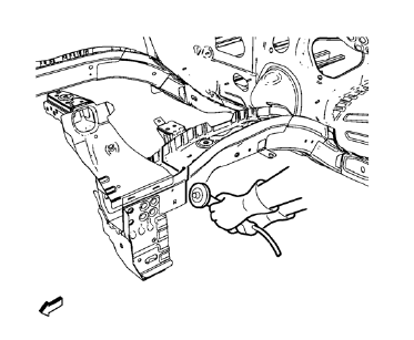
Note: Do not damage internal reinforcement of front compartment side rail.
- Cut the panel where sectioning is to be performed.
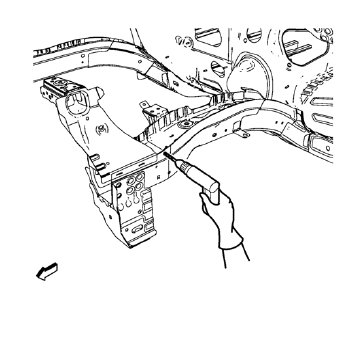
Note: Left side only.
- Locate and mark all the necessary factory welds of the front compartment front rail.
- Drill all factory welds. Note the number and location of welds for installation of the service assembly.
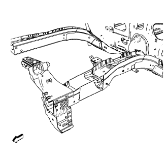
- Remove the damaged front compartment front rail.
 Front Compartment Side Rail Sectioning (Short, MAG-Welding)
Note: According to different corrosion warranties, only the
regional mandatory joining methods are allowed. ...
 Installation Procedure
Cut the front compartment front rail in corresponding locations to fit
the remaining original panel. The sectioning joint should be
trimmed to allow a gap of one-and-one-half-times the met ...
Other materials:
Rear Compartment Lid Emblem/Nameplate Replacement (Bowtie)
Rear Compartment Lid Emblem Assembly
Caution: Refer to Exterior Trim Emblem Removal Caution in the
Preface section.
Procedure
The part and surface should be 21°C (70°F) prior to installation. The
vehicle should remain 21°C (70°F) for
one hour after assembly to allow adhesive to deve ...
Bluetooth
Overview
For vehicles equipped with Bluetooth capability, the system can interact with
many cell phones and devices, allowing:
• Placing and receiving hands-free calls.
• Sharing of the cell phone’s address book or contact list with the vehicle. The
phone book will only display when that phon ...
Vehicle Access
Specifications
Door Lock/Indicator Schematics
Door Control Module Schematics
Release Systems Schematics
Fuel Tank Filler Door Lock Actuator Replacement
Preliminary Procedure
Remove the fuel tank filler housing. Refer to Fuel Tank Filler Pipe Housing ...
