
Chevrolet Cruze Repair Manual: Removal Procedure
Warning: Refer to Approved Equipment for Collision Repair Warning in the Preface section.
Warning: Refer to Collision Sectioning Warning in the Preface section.
Warning: Refer to Glass and Sheet Metal Handling Warning in the Preface section.
- Disable the SIR System. Refer to SIR Disabling and Enabling.
- Disconnect the negative battery cable. Refer to Battery Negative Cable Disconnection and Connection.
- Remove all related panels and components.
- Visually inspect the damage. Repair as much of the damage as possible.
- Remove the sealers and anti-corrosion materials from the repair area, as necessary. Refer to Anti-Corrosion Treatment and Repair.
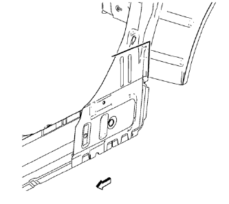
- Create cut lines on the body side inner panel.
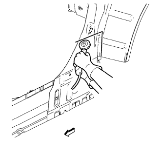
Note: Do not damage any inner panels or reinforcements.
- Cut the panel where sectioning is to be performed.
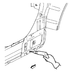
- Locate and mark all the necessary factory welds of the body side inner panel.
- Drill all factory welds.
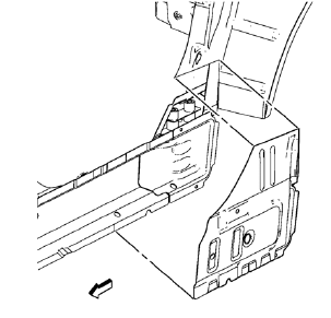
- Remove the body side inner panel.
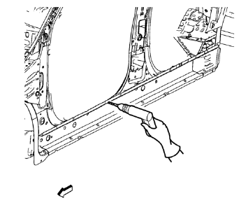
- Locate and mark all the necessary factory welds of the rocker inner panel.
- Drill all factory welds.
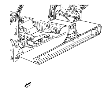
- Remove the damaged rocker inner panel.
 Rocker Inner Panel Replacement (MIG-Brazing)
Note: According to different corrosion warranties, only the
regional mandatory joining methods are allowed. ...
 Installation Procedure
Align the rocker inner panel.
Clean and prepare the attaching surfaces for spot welding.
Apply structural adhesive to all attaching surfaces.
Position the rocker inner panel on ...
Other materials:
Instrument Panel Upper Trim Pad Insert Replacement
Preliminary Procedure
Remove the instrument panel. Refer to Instrument Panel Assembly Replacement.
Instrument Panel Upper Trim Pad Insert Screw (Qty: 6)
Caution: Refer to Fastener Caution in the Preface section.
Tighten
2.5 N·m (22 lb in)
Instrument Panel Upper Trim Pad Insert Asse ...
Where to Put the Restraint
According to accident statistics, children and infants are safer when properly
restrained in a child restraint system or infant restraint system secured in a rear
seating position.
We recommend that children and child restraints be secured in a rear seat, including:
an infant or a child ridin ...
Daytime Running Lamps (DRL)
Daytime Running Lamps can make it easier for others to see the front of your
vehicle during the day. Fully functional daytime running lamps are required on all
vehicles first sold in Canada.
A light sensor on top of the instrument panel makes the DRL work, so be sure
it is not covered.
The D ...
