Chevrolet Cruze Repair Manual: Removal Procedure
Warning: Refer to Approved Equipment for Collision Repair Warning in the Preface section.
Warning: Refer to Glass and Sheet Metal Handling Warning in the Preface section.
- Disable the SIR System. Refer to SIR Disabling and Enabling.
- Disconnect the negative battery cable. Refer to Battery Negative Cable Disconnection and Connection.
- Remove all related panels and components.
- Visually inspect the damage. Repair as much of the damage as possible.
- Remove the sealers and anti-corrosion materials from the repair area, as necessary. Refer to Anti-Corrosion Treatment and Repair.

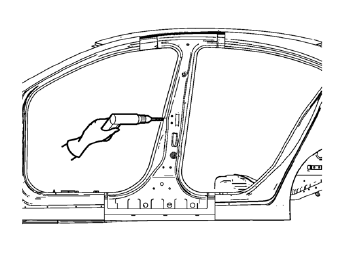
- Locate and mark all the necessary factory welds of the body lock pillar outer panel reinforcement.
- Drill all factory welds. Note the number and location of welds for installation of the service assembly.

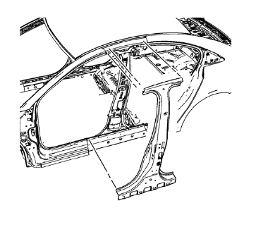
- Remove the damaged body lock pillar outer panel reinforcement.
 Body Lock Pillar Outer Panel Reinforcement Replacement (MIG-Brazing)
Note: According to different corrosion warranties, only the
regional mandatory joining methods are allowed. ...
 Installation Procedure
Prepare all mating surfaces as necessary.
Align the body lock pillar outer panel reinforcement.
Create 8 x 24 mm (5/16 x 15/16 in) slots for MIG-brazing upper (1) and
lower (2).
Cl ...
Other materials:
Backup Lamp Replacement
Preliminary Procedures
Remove the rear compartment sill trim plate. Refer to Rear Compartment
Sill Trim Plate Replacement.
Disconnect the electrical harness connector from the backup lamp socket.
Back Up Lamp Nut (Qty: 4)
Caution: Refer to Fastener Caution in the Preface ...
Washer Fluid
What to Use
When windshield washer fluid is needed, be sure to read the manufacturer's instructions
before use. If operating the vehicle in an area where the temperature may fall below
freezing, use a fluid that has sufficient protection against freezing.
Adding Washer Fluid
Open the ca ...
Installation Procedure
Apply structural adhesive on the flanges of the front side door inner
panel where the front side door outer panel bears on.
Align the front side door outer panel.
Verify the fit of the front side door outer panel.
Clamp the front side door outer panel into position.
Pre-f ...
