Chevrolet Cruze Repair Manual: Removal Procedure
Warning: Refer to Approved Equipment for Collision Repair Warning in the Preface section.
Warning: Refer to Glass and Sheet Metal Handling Warning in the Preface section.
- Disable the SIR System. Refer to SIR Disabling and Enabling.
- Disconnect the negative battery cable. Refer to Battery Negative Cable Disconnection and Connection.
- Remove all related panels and components.
- Visually inspect the damage. Repair as much of the damage as possible.
- Remove the sealers and anti-corrosion materials from the repair area, as necessary. Refer to Anti-Corrosion Treatment and Repair.
- Locate and mark all factory welds. Note the number and location of welds for installation of the service assembly.
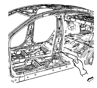
- Drill all factory welds lower.
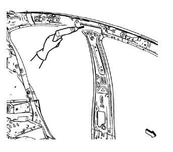
- Drill all factory welds upper.
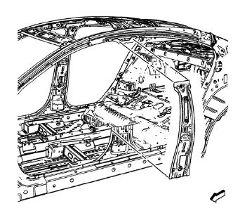
- Remove the damaged body lock pillar inner panel.
 Body Lock Pillar Inner Panel Replacement (MIG-Brazing)
Note: According to different corrosion warranties, only the
regional mandatory joining methods are allowed. ...
 Installation Procedure
Create 6 x 20 mm (4/16 x 11/16 in) slots for MIG-brazing along the upper
edges of the service panel as noted from the original
panel.
Clean and prepare the attaching surfaces for brazing ...
Other materials:
Rear Brake Rotor Replacement
Special Tools
CH 41013 Rotor Resurfacing Kit
CH 42450-A Wheel Hub Resurfacing Kit
For equivalent regional tools, refer to Special Tools.
Removal Procedure
Warning: Refer to Brake Dust Warning in the Preface section.
Remove rear brake caliper bracket. Refer to Rear Brake Caliper Br ...
Removal Procedure
Warning: Refer to Approved Equipment for Collision Repair Warning in the
Preface section.
Warning: Refer to Collision Sectioning Warning in the Preface section.
Warning: Refer to Glass and Sheet Metal Handling Warning in the Preface section.
Disable the SIR System. Refer to SIR Dis ...
Brakes
This vehicle has front disc brakes and could have rear drum brakes or rear disc
brakes.
Disc brake pads have built-in wear indicators that make a high-pitched warning
sound when the brake pads are worn and new pads are needed.
The sound can come and go or be heard all the time the vehicle is m ...
