
Chevrolet Cruze Repair Manual: Installation Procedure
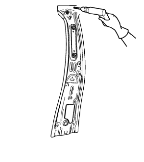
- Create 6 x 20 mm (4/16 x 11/16 in) slots for MIG-brazing along the upper edges of the service panel as noted from the original panel.
- Clean and prepare the attaching surfaces for brazing and spot welding.
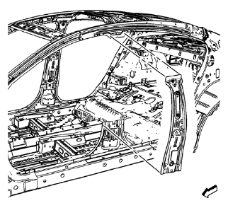
- Position the body lock pillar inner panel on the vehicle.
- Verify the fit of the panel.
- Clamp the body lock pillar inner panel into position.
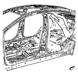
- Braze accordingly the body lock pillar inner panel upper.
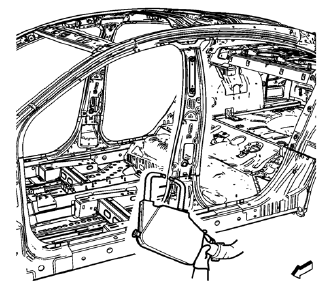
- Spot weld accordingly the body lock pillar inner panel lower.
- Apply the sealers and anti-corrosion materials to the repair area, as necessary. Refer to Anti-Corrosion Treatment and Repair.
- Paint the repaired area. Refer to Basecoat/Clearcoat Paint Systems.
- Install all related panels and components.
- Connect the negative battery cable. Refer to Battery Negative Cable Disconnection and Connection.
- Enable the SIR system. Refer to SIR Disabling and Enabling.
 Removal Procedure
Warning: Refer to Approved Equipment for Collision Repair Warning in the
Preface section.
Warning: Refer to Glass and Sheet Metal Handling Warning in the Preface section.
Disable the SIR Syst ...
 Rocker Outer Panel Sectioning (MAG-Welding)
Note: According to different corrosion warranties, only the
regional mandatory joining methods are allowed. ...
Other materials:
Rear Side Door Window Regulator Motor Replacement
Preliminary Procedure
Remove the rear side door window regulator. Refer to Rear Side Door Window
Regulator Replacement.
Rear Side Door Window Regulator Motor Screw (Qty: 3)
Caution: Refer to Fastener Caution in the Preface section.
Tighten
9 N·m (80 lb in)
Rear Side Door Window R ...
Removal Procedure
Warning: Refer to Approved Equipment for Collision Repair Warning in the
Preface section.
Disable the SIR System. Refer to SIR Disabling and Enabling.
Disconnect the negative battery cable. Refer to Battery Negative Cable
Disconnection and Connection.
Remove all related panels and compo ...
Installation Procedure
Position the front brake shield (2) and front wheel bearing/hub (1)
assembly in the steering knuckle.
Caution: Refer to Fastener Caution in the Preface section.
Install the NEW front wheel bearing/hub bolts (1).
Tighten the bearing/hub bolts (1) in 3 passes. Use the EN-45059 k ...
