Chevrolet Cruze Repair Manual: Removal Procedure
Warning: Refer to Approved Equipment for Collision Repair Warning in the Preface section.
Warning: Refer to Glass and Sheet Metal Handling Warning in the Preface section.
- Disable the SIR System. Refer to SIR Disabling and Enabling.
- Disconnect the negative battery cable. Refer to Battery Negative Cable Disconnection and Connection.
- Remove all related panels and components.
- Visually inspect the damage. Repair as much of the damage as possible.
- Remove the sealers and anti-corrosion materials from the repair area, as necessary. Refer to Anti-Corrosion Treatment and Repair.
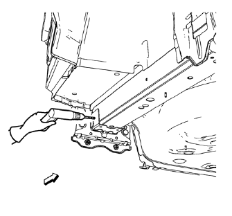
- Locate and mark all the necessary factory welds of the rear end panel plate.
Note: Note the number and location of welds for installation of the service assembly.
- Drill all factory welds.
- Remove the underbody rear side rail reinforcement.
 Underbody Rear Side Rail Reinforcement Replacement (MAG-Welding)
Note: According to different corrosion warranties, only the
regional mandatory joining methods are allowed. ...
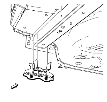
 Installation Procedure
Note: If the location of the original plug weld holes can
not be determined, space the plug weld holes every 40 mm (1½ in).
Drill 8 mm (5/16 in) for plug welding along the edges of th ...
Other materials:
Installation Procedure
Clean and prepare the attaching surfaces for welding.
Apply one-part windshield urethane adhesive as noted from the original
panel.
Position the roof panel (1) on the
vehicle.
Verify the fit of the panel.
Clamp the panel into position.
Spot weld accor ...
Courtesy/Illuminated Entry Lamps
The following lamps may be manually turned ON by placing the interior lamp
switch in the ON position, or by opening a door while the
switch is in the AUTO position.
The dome lamp
The liftgate lamps
Courtesy lamps
The courtesy lamp supply voltage circuit of the body control module (BCM) ...
Aluminum Wheel Porosity Repair
Remove the tire and wheel. Refer to Tire and Wheel Removal
and Installation.
Inflate the tire to the manufactures specified pressure as stated on the
tire.
Submerge the tire/wheel into a water bath in order to locate the leak.
Inscribe a mark on the wheel in order to indic ...
